Variable class characteristic amplifier

a characteristic amplifier and amplifier technology, applied in push-pull amplifiers, phase splitters, amplifiers with field-effect devices, etc., can solve the problems of reducing the stability of typical class e amplifiers into high-voltage standing wave ratio load mismatches, reducing the efficiency of typical class e amplifiers, and preventing spurious outputs. , the effect of improving circuit stability

Active Publication Date: 2013-01-01
MKS INSTR INC
View PDF111 Cites 59 Cited by
  • Summary
  • Abstract
  • Description
  • Claims
  • Application Information

AI Technical Summary

Benefits of technology

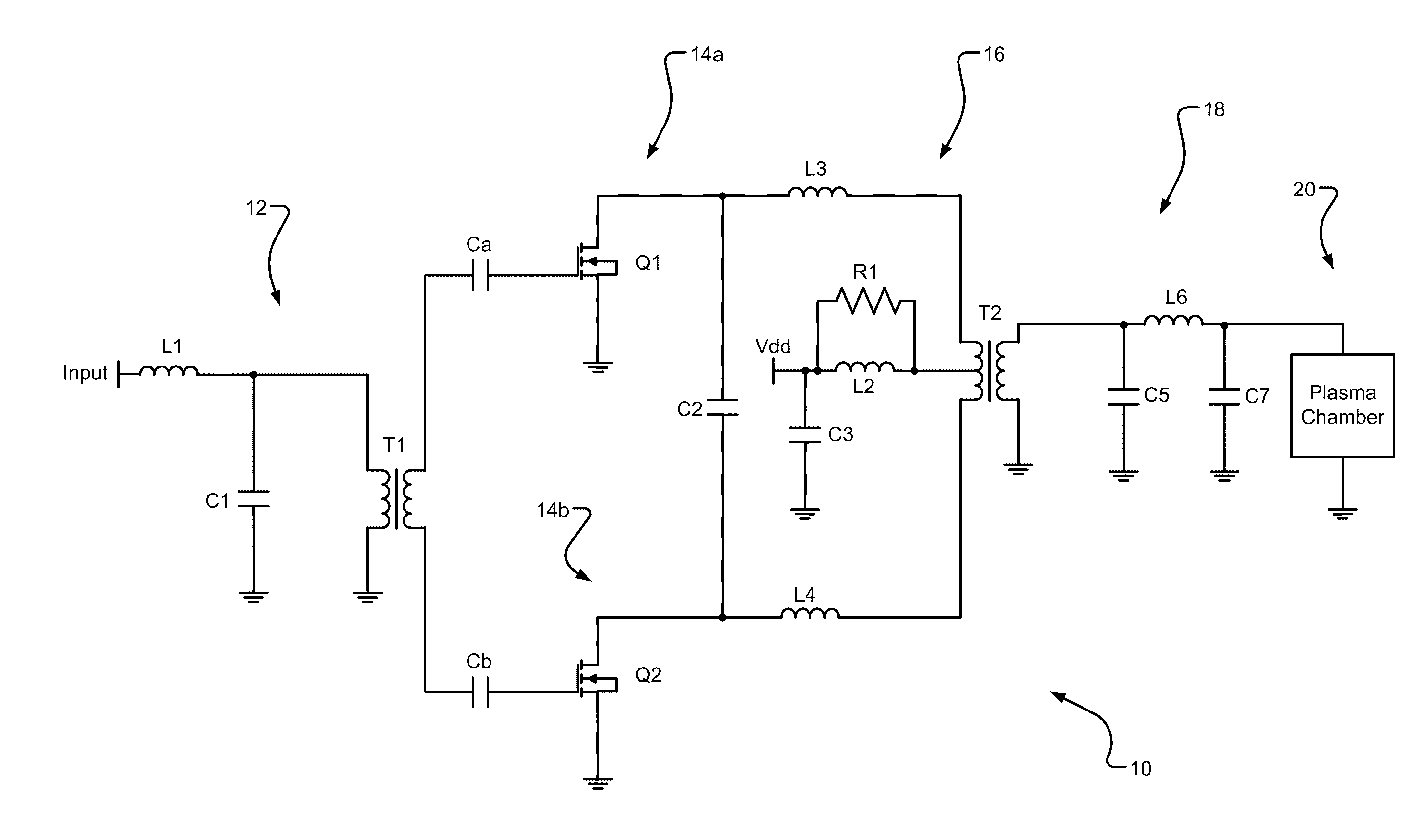
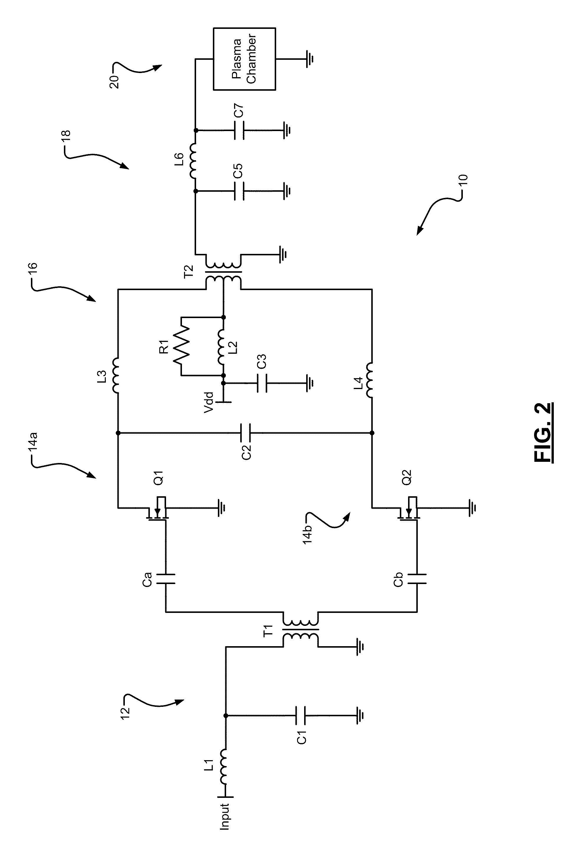
[0062]In various embodiments, during high output power and when there is a high VSWR load, the transients and out of band energy can appear at the center tap of the output transformer T2, whereas the fundamental does not. In various embodiments, a R1 resistor value of, by way of non-limiting example, between 5 to 10Ω will effectively dump some of the reflected power from the high VSWR load, thus helping to isolate and protect the push-pull transistors from excessive high voltages and currents. This improves circuit stability and helps to prevent spurious outputs.
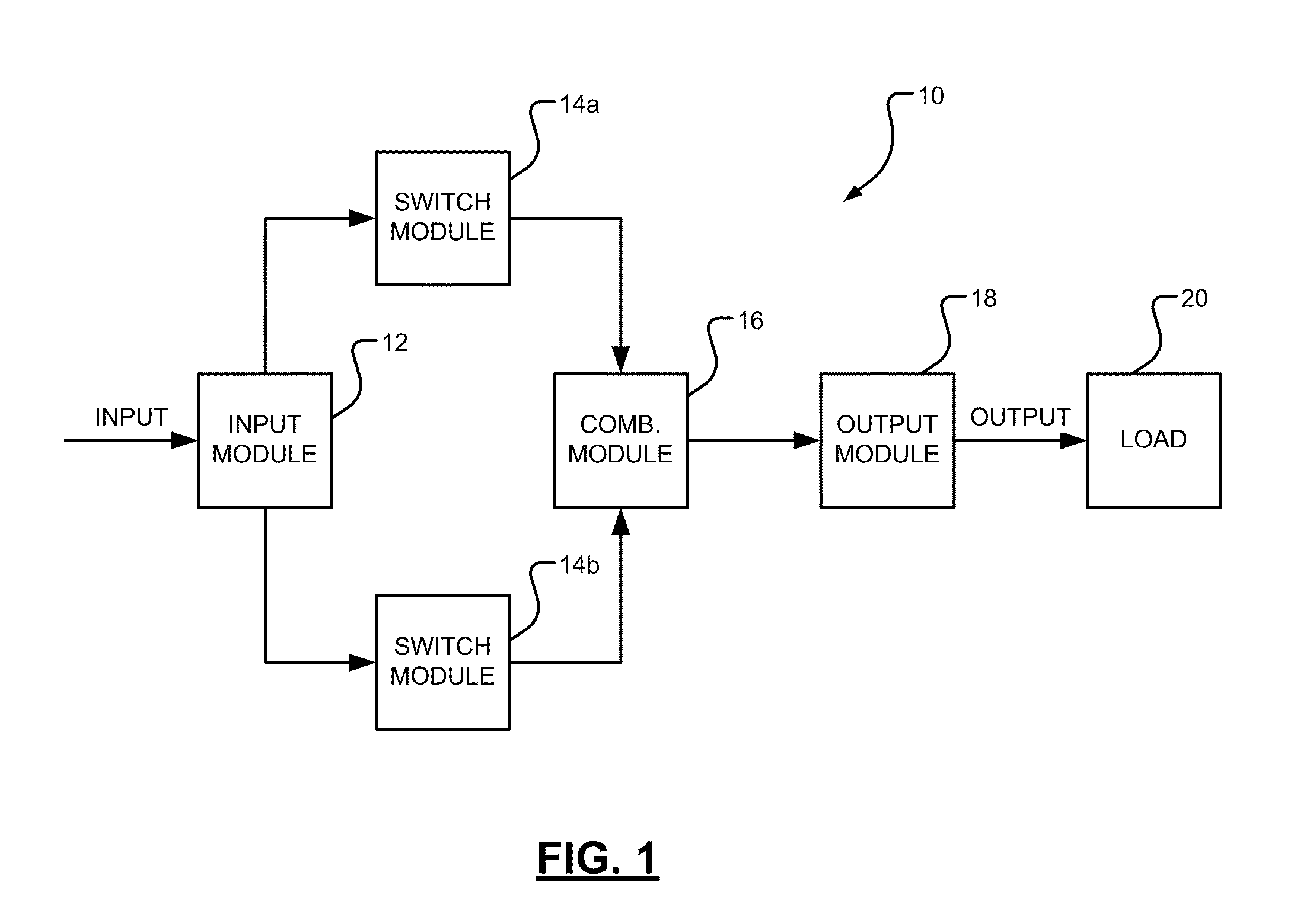
[0063]In various embodiments, the output modules 18, 76 components are tuned to produce the desired class characteristic operation with its useful efficiency and load pull stability aspects. In general, the higher the conduction angle of switch modules 14a, 14b, 74 and the longer the outputs of switch modules 14a, 14b, 74 are in a matched impedance on state, the greater the margin of stability will be, and hence the lower the probability of spurious outputs during high VSWR loads.
[0064]Various embodiments provide higher efficiency which translates to lower running costs and better reliability. Further, flexible tuning between Class AB and Class E characteristics provides more responsive power control. While operating in Class E characteristic mode, the various embodiments have softer limiting at the top of the dynamic power range which reduces the responsiveness of the system output power control, which may not be desirable in some applications. Further, various embodiments provide a lower cost design because of the minimalist design with fewer components. The less complex variable class characteristic power amplifier 10, 70 provides for a reduced size, which can result in improved power density. Various embodiments also provide better reliability by reduced switch module 14a, 14b, 74 transistor stress and fewer components.
[0065]Various embodiments also impr...

Problems solved by technology

RF power amplifiers and generators are thus not typically interchangeable or easily modified to accommodate various applications.
In conventional power amplifiers, class AB efficiency is limited to about 70%.
Typical Class E amplifiers are typically less stable into ...

Method used


Image

  • Variable class characteristic amplifier
  • Variable class characteristic amplifier
  • Variable class characteristic amplifier

Examples


Embodiment Construction

[0029]Example embodiments will now be described more fully with reference to the accompanying drawings.

[0030]Example embodiments are provided so that this disclosure will be thorough, and will fully convey the scope to those who are skilled in the art. Numerous specific details are set forth such as examples of specific components, devices, and methods, to provide a thorough understanding of embodiments of the present disclosure. It will be apparent to those skilled in the art that specific details need not be employed, that example embodiments may be embodied in many different forms and that neither should be construed to limit the scope of the disclosure. In some example embodiments, well-known processes, well-known device structures, and well-known technologies are not described in detail.

[0031]The terminology used herein is for the purpose of describing particular example embodiments only and is not intended to be limiting. As used herein, the singular forms “a,”“an,” and “the” ...


PUM


Abstract

A power amplifier (PA) adjustably operable between two classes of operation. The range of operation lies in a range of operation between a conventional, linear, conjugately matched Class AB characteristic amplifier and a higher efficiency switching Class E characteristic amplifier. A circuit topology having a push-pull configuration that allows a Class E characteristic of operation.

Description

CROSS-REFERENCE TO RELATED APPLICATIONS[0001]This application claims the benefit of U.S. Provisional Application No. 61 / 320,541, filed on Apr. 2, 2010. The entire disclosure of the above application is incorporated herein by reference.FIELD[0002]The present disclosure relates to power amplifiers and to power amplifiers having characteristics of more than one class of amplifier.BACKGROUND[0003]This section provides background information related to the present disclosure which is not necessarily prior art.[0004]Various industries use radio frequency (RF) to drive plasma chambers in order to fabricate various components such as integrated circuits, solar panels, compact disks (CDs), digital versatile (or video) discs (DVDs), and the like. Each fabrication process can vary depending upon the particular component being manufactured. The various processes often call for delivery of RF energy at varying frequencies, power levels, and efficiencies.[0005]Present RF power delivery systems te...

Claims


Application Information

Patent Timeline
IPC IPC(8): H03F3/217
CPCH03F1/0205H03F1/565H03F3/2176H03F3/265H03F2200/537H03F2200/378H03F2200/387H03F2200/391H03F1/02H03F1/56H03F3/217H03F3/26
Inventor OWEN, CHRISTOPHER MICHAELCHAWLA, YOGENDRA K.
Owner MKS INSTR INC
Why Eureka
Try Eureka