Power converting device and synchronous rectifier control circuit

a technology of converting device and synchronous rectifier, which is applied in the direction of electric variable regulation, process and machine control, instruments, etc., can solve the problems of only suitable control method for dcm, inconvenient control method, and energy loss incurred from conduction of rectifier diodes, etc., and achieve the effect of promoting circuit stability

Active Publication Date: 2015-08-04
LITE ON TECH CORP
View PDF4 Cites 4 Cited by
  • Summary
  • Abstract
  • Description
  • Claims
  • Application Information

AI Technical Summary

Benefits of technology

[0012]Therefore, an object of the present invention is to provide a power converting device which ensures that, no matter which one of the CCM and DCM the power converting device operates, the switches at the primary side and the secondary side may be prevented from conducting at the same time. Moreover, when the load varies rapidly or when the power converting device is started up or shut down, generation of the reverse current may also be prevented, so as to promote circuit stability.

Problems solved by technology

However, a considerable energy loss is incurred from conduction of the rectifier diodes.
However, the aforementioned control method is only suitable for the DCM.
However, owing to the RC time constant of the RC trigger, the aforementioned solution is not suitable for a situation where a load varies rapidly.
Nevertheless, the capacitor takes a response time to charge and discharge, such that when the load varies rapidly, for example, referring to FIG. 2, within a time interval t1 when the load varies from a heavy load to a light load, the synchronous rectifier controller may not catch up with switching changes of the main switch Q1 because it takes time for the capacitor to charge and discharge.
The synchronous rectifier switch Q2 may be damaged by the voltage spike Vsp if voltage tolerance thereof is insufficient.
When the power converter is started up or shut down, the output current ILO, may have a moment of zero current, such that the synchronous rectifier switch Q2 may be damaged by the voltage spike Vsp, if not turned off in time.
However, the synchronous rectifier forward converter disclosed in the U.S. patent is also incapable of preventing generation of the reverse current under the condition that the load varies rapidly.

Method used


Image

  • Power converting device and synchronous rectifier control circuit
  • Power converting device and synchronous rectifier control circuit
  • Power converting device and synchronous rectifier control circuit

Examples


Embodiment Construction

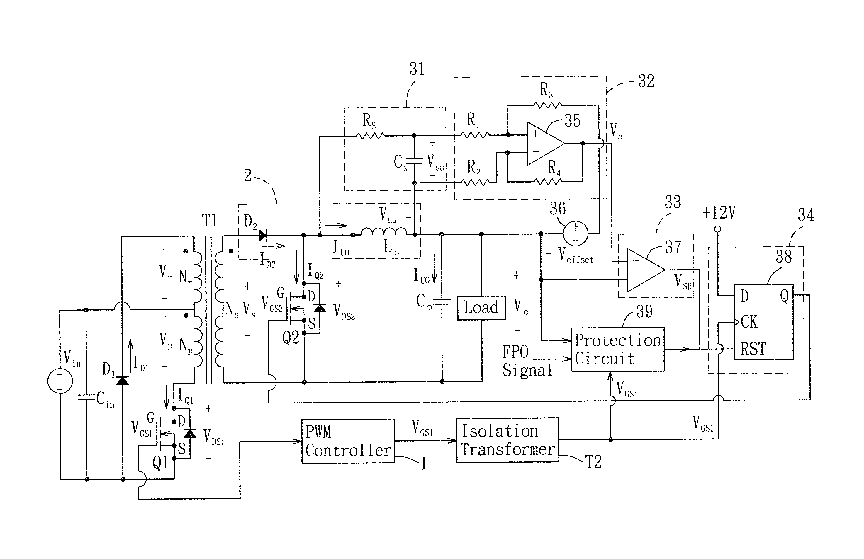
[0025]Referring to FIG. 3, an isolation forward power converter is given as an example for a first preferred embodiment of a power converting device according to the present invention. The first preferred embodiment of the power converting device comprises a transformer T1, a first switch (i.e., a main switch) Q1 disposed at a primary side of the transformer T1, a pulse-width modulation (PWM) controller 1 adapted to control conduction and non-conduction of the first switch Q1, a rectifier-filter circuit 2 disposed at a secondary side of the transformer T1, a second switch (i.e., a synchronous rectifier switch) Q2, and a synchronous rectifier control circuit 3 adapted to control conduction and non-conduction of the second switch Q2.

[0026]The transformer T has a primary winding Np and a secondary winding Ns. The primary winding Np has a first end coupled electrically to a high voltage side of an input source for receiving an input voltage Vin. The secondary winding NS generates an ind...


PUM


Abstract

A power converting device includes a main switch, a synchronous rectifier switch, a rectifier-filter circuit which outputs an output voltage, and a synchronous rectifier control circuit which includes a sampling circuit coupled to the rectifier-filter circuit for outputting a voltage variation signal, a differential amplifier circuit that outputs an amplified signal by adding the output voltage and an offset voltage to the voltage variation signal attenuated thereby, and a comparison circuit that compares the amplified signal with the output voltage so as to output a trigger signal, such that the synchronous rectifier switch is turned on when the main switch is turned off, and is turned off prior to conduction of the main switch.

Description

CROSS-REFERENCE TO RELATED APPLICATION[0001]This application claims priority of Taiwanese Patent Application No. 101140350, filed on Oct. 31, 2012.BACKGROUND OF THE INVENTION[0002]1. Field of the Invention[0003]The invention relates to a power converting device, more particularly to a power converting device which adopts a synchronous rectifier circuit.[0004]2. Description of the Related Art[0005]In a conventional forward power converter, a main switch is disposed at the primary side thereof, and a rectifier circuit which is composed of rectifier diodes is disposed at a secondary side thereof. However, a considerable energy loss is incurred from conduction of the rectifier diodes. Therefore, referring to FIG. 1, a synchronous rectifier switch (MOS transistor switch) Q2 is usually adopted to replace the rectifier diodes at the secondary side of a transformer T1 of an existing forward power converter, and a synchronous rectifier controller 6 is used to control conduction and non-condu...

Claims


Application Information

Patent Timeline
Patent Type & Authority Patents(United States)
IPC IPC(8): H02M3/137H02M3/335H02M1/36H02M1/00
CPCH02M1/36H02M3/33592Y02B70/1475H02M2001/0019H02M1/0019Y02B70/10
Inventor TSENG, PO-JUNGHUANG, CHIN-CHUANLIN, SIN-LILO, YU-KANGCHIU, HUANG-JENLIN, JING-YUAN
Owner LITE ON TECH CORP
Why Eureka
Try Eureka