Reflection-detector sensor position indicator

a technology of reflection detector and position indicator, which is applied in the field of reflection detector sensor position indicator, can solve problems such as critical missed

Active Publication Date: 2013-01-01
JPMORGAN CHASE BANK NA
View PDF243 Cites 571 Cited by
  • Summary
  • Abstract
  • Description
  • Claims
  • Application Information

AI Technical Summary

Problems solved by technology

Problems arise if a pulse oximeter or other blood parameter monitor is connected to an optical sensor that is not properly positioned on a tissue site or becomes partially or completely dislodged from a patient, a so-called “probe off” condition.
Probe-off errors are serious because a blood parameter monitor may still display a normal measurement, potentially leading to critical missed events, such as a patient desaturation.

Method used


Image

  • Reflection-detector sensor position indicator
  • Reflection-detector sensor position indicator
  • Reflection-detector sensor position indicator

Examples


Embodiment Construction

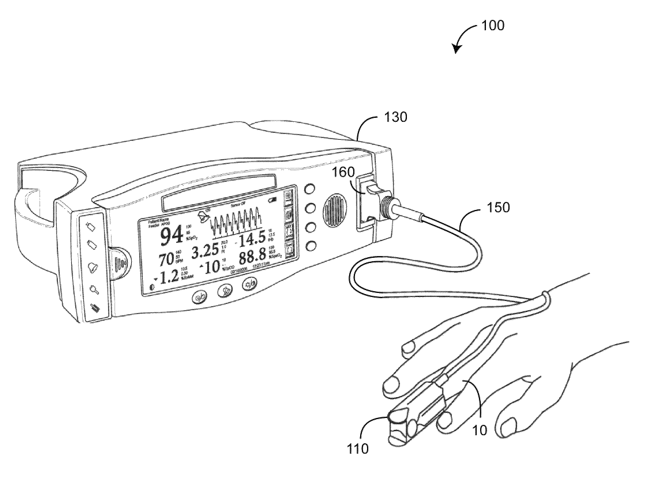
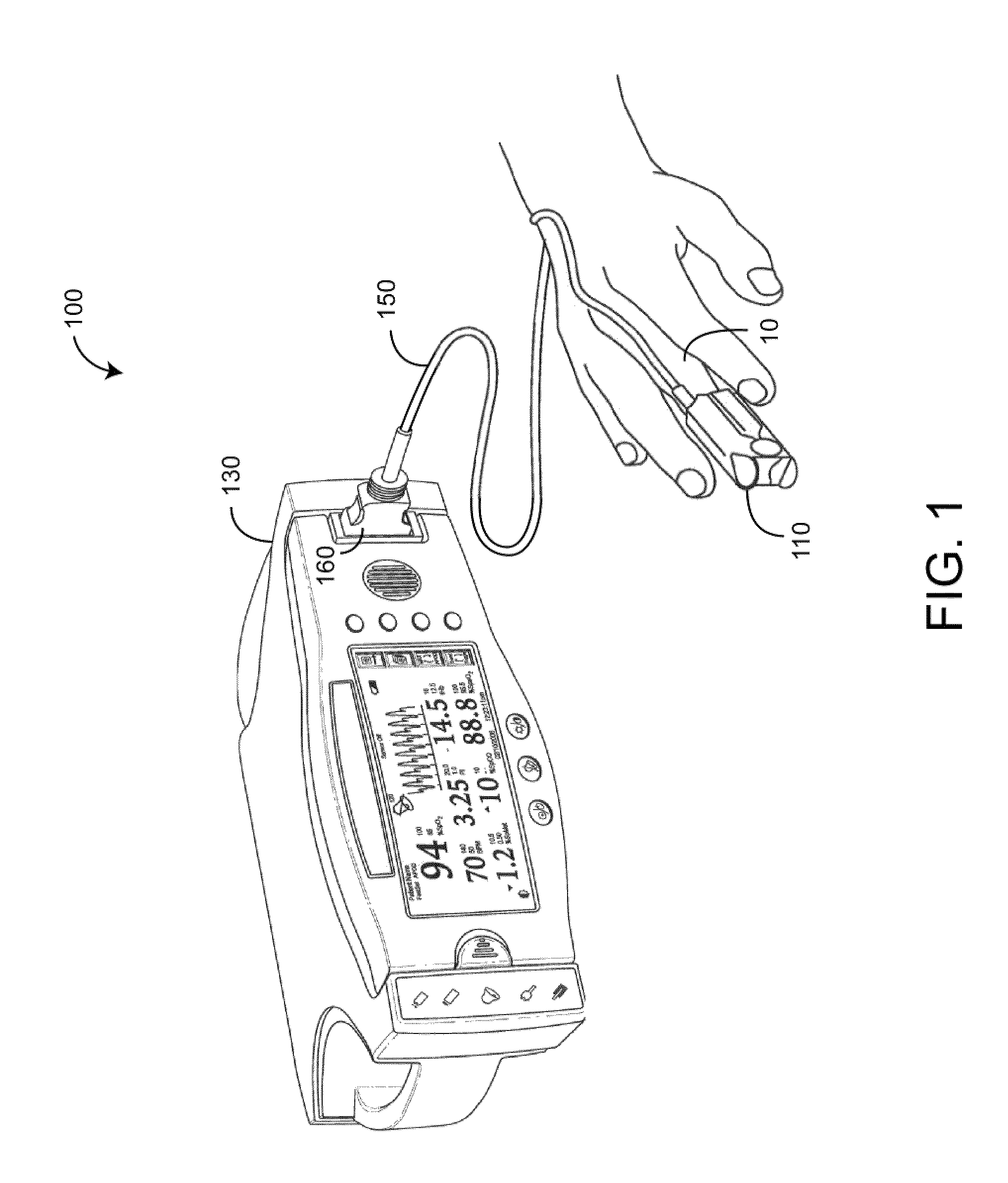
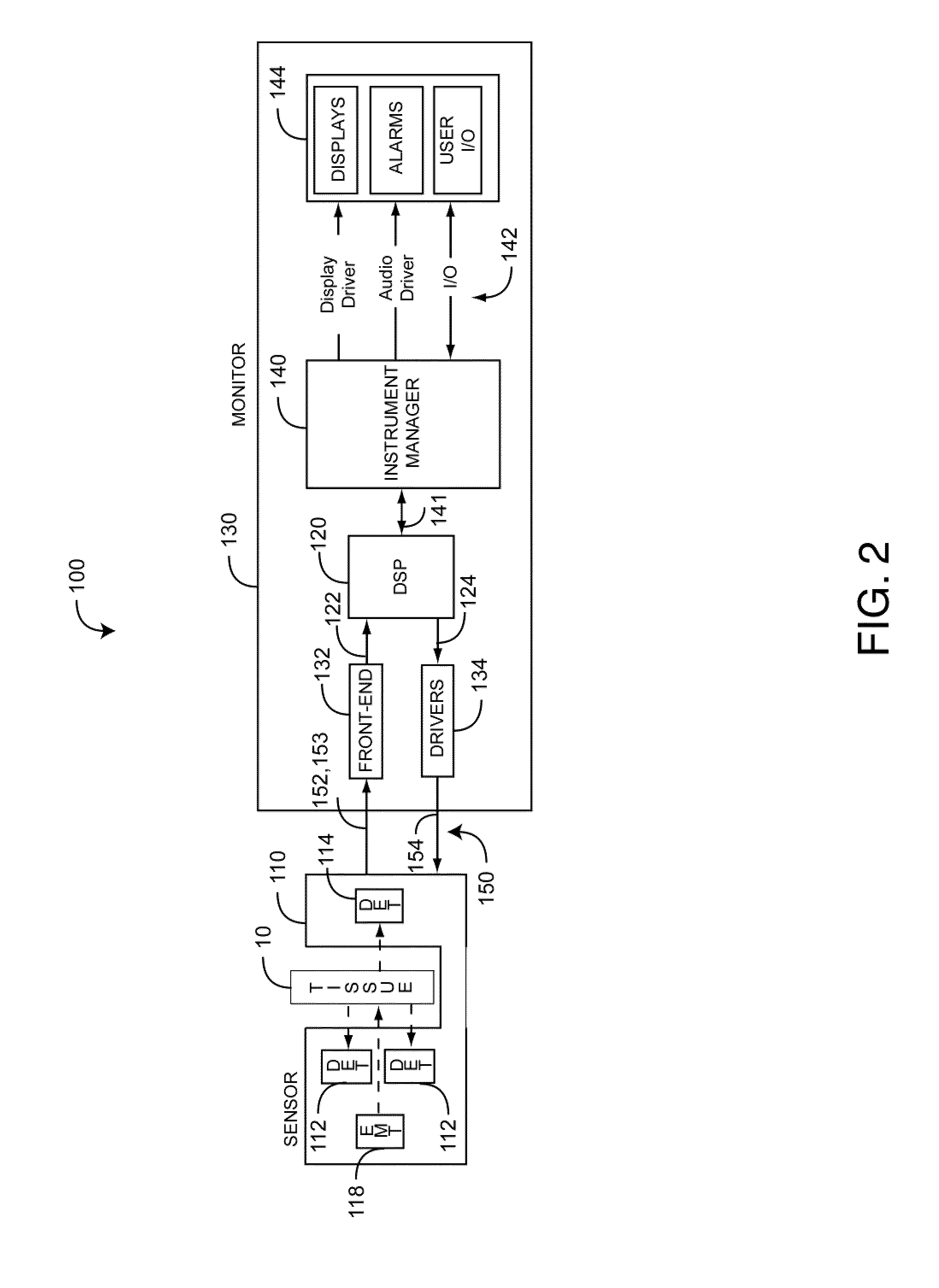
[0016]FIGS. 1-2 illustrate a physiological measurement system 100 which measures blood constituents and related parameters, such as oxygen saturation, pulse rate, perfusion index (PI), pleth variability index (PVI™), HbCO, HbMet and Hbt, to name a few. The physiological measurement system 100 includes an optical sensor 110 applied to a tissue site 10, a physiological monitor 130 and a cable 150 that physically and electrically connects the sensor 110 to the monitor 130. Advantageously, the physiological measurement system 100 also utilizes a sensor position indicator responsive to improper placement of the sensor 110 on a finger or other tissue site 10, as described in detail below.

[0017]As shown in FIGS. 1-2, the monitor 130 communicates with the sensor 110 to receive one or more sensor signals indicative of one or more physiological parameters. In particular, a digital signal processor (DSP) 120 outputs digital control signals 124 to drivers 134 and inputs digital data 122 from th...


PUM


Abstract

A reflection-detector sensor position indicator comprises emitters that transmit light having a plurality of wavelengths. A detector outputs a sensor signal. At least one reflection detector outputs at least one sensor position signal. An attachment assembly attaches the emitters, the detector and the reflection detector onto a tissue site. A sensor-on condition indicates that the attachment assembly has positioned the emitters generally centered over a fingernail, the detector on a fingertip opposite the fingernail and the reflection detector over the fingernail. The sensor signal, in the sensor-on condition, is at least substantially responsive to the emitter transmitted light after attenuation by pulsatile blood flow perfused within a fingernail bed underneath the fingernail. The sensor position signal, in the sensor-on condition, is at least substantially responsive to the emitter transmitted light after reflection off of the fingernail.

Description

CROSS-REFERENCE TO RELATED APPLICATIONS[0001]The present application claims priority benefit under 35 U.S.C. §119(e) to U.S. Provisional Patent Application Ser. No. 61 / 104,969, filed Oct. 13, 2008, titled Reflection-Detector Sensor Position Indicator, hereby incorporated by reference herein.BACKGROUND OF THE INVENTION[0002]Pulse oximetry is a technique that utilizes a noninvasive sensor to determine a person's oxygen status. An optical sensor used in pulse oximetry has light emitting diodes (LEDs) that transmit optical radiation of red and infrared wavelengths into a tissue site. A detector in the sensor responds to the intensity of the optical radiation after attenuation by pulsatile arterial blood flowing within the tissue site. Based on this response, a processor determines measurements for SpO2 and pulse rate among other parameters. Pulse oximeters capable of reading through motion induced noise are available from Masimo Corporation (“Masimo”) of Irvine, Calif. Moreover, portabl...

Claims


Application Information

Patent Timeline
Patent Type & Authority Patents(United States)
IPC IPC(8): A61B5/00
CPCA61B5/061A61B5/14552A61B5/6826A61B5/6838A61B5/0205A61B5/0261A61B5/743A61B5/14551A61B5/1495A61B5/6844A61B5/7405A61B5/14546A61B5/02416
Inventor LAMEGO, MARCELO
Owner JPMORGAN CHASE BANK NA
Why Eureka
Try Eureka