Atom-interferometric, stepped gravity gradient measuring system

a gravity gradient and gradiometer technology, applied in the field of gravity gradiometers, can solve the problems of lack of portability and rapidity, low failure rate, and low failure rate of gradiometers, and achieve the effects of improving the accuracy of gradient measurements, reducing cost and maintenance, and high signal-to-noise ratio

Inactive Publication Date: 2013-01-08
LOCKHEED MARTIN CORP
View PDF14 Cites 10 Cited by
  • Summary
  • Abstract
  • Description
  • Claims
  • Application Information

AI Technical Summary

Benefits of technology

[0009]The three gradiometers in the overall measuring system are mounted orthogonally with respect to one another on a stable, local-level platform, in order to achieve a full-tensor measuring system. In accordance with the illustrative embodiment, the three gradiometers are mounted in an orthogonal umbrella coordinate system on the local-level platform, where the measuring reference plane of each gradiometer is preferentially angled 35.26 degrees above the horizontal of the local-level. This ensures that all gradiometers experience a common component of the g-vector, thereby optimizing the operation of the AI-based accelerometer pairs. As with the individual gradiometers, the measuring system can be step-rotated as an overall unit around an axis perpendicular to the local level reference.
[0010]The atom interferometry that is featured in the illustrative embodiment is beneficial for various reasons. One benefit is the increased accuracy in the gradient measurements, which is based on the interference of atom waves within a formed, coherent atom cloud. The atom densities in the atom cloud yield extremely high signal-to-noise ratios during the measurements. Further in respect of the accuracy achieved, the use of an atomic proof mass, rather than a conventional proof mass, ensures the material properties between proof masses will be identical. Another benefit is the reduced cost and maintenance on account of the fewer moving parts within each gradiometer, relative to some systems in the prior art.
[0011]As enabled by atom interferometry, the stepped movement featured in the illustrative embodiment eliminates the need for the continuous rotation that is inherent in some techniques of the prior art. The stepped movement renders unnecessary the use of problematic slip rings for electrical contacts or of cables that can get twisted up. Additionally, because there are no springs that can continue to oscillate, a high slewing rate can be used to move the accelerometer pairs of each gradiometer from one orientation to the next. And because of the stepping manner in which each gradiometer, as well as the overall system, can be rotated and stopped for a measurement, various techniques for reducing noise, correcting alignment errors between the accelerometer pairs, and providing calibration across the gradiometers can be utilized.

Problems solved by technology

This type of gradiometer, however, has its limitations which include lack of portability and rapidity.
Because of the complement of hardware required, it is relatively costly to engineer a low failure rate with high signal-to-noise performance for this type of gradiometer system.
Additionally, the accelerometers that are utilized are typically under-damped, thereby making the gradiometers very fragile and sensitive to small disturbances in the rotation rate.

Method used


Image

  • Atom-interferometric, stepped gravity gradient measuring system
  • Atom-interferometric, stepped gravity gradient measuring system
  • Atom-interferometric, stepped gravity gradient measuring system

Examples


Embodiment Construction

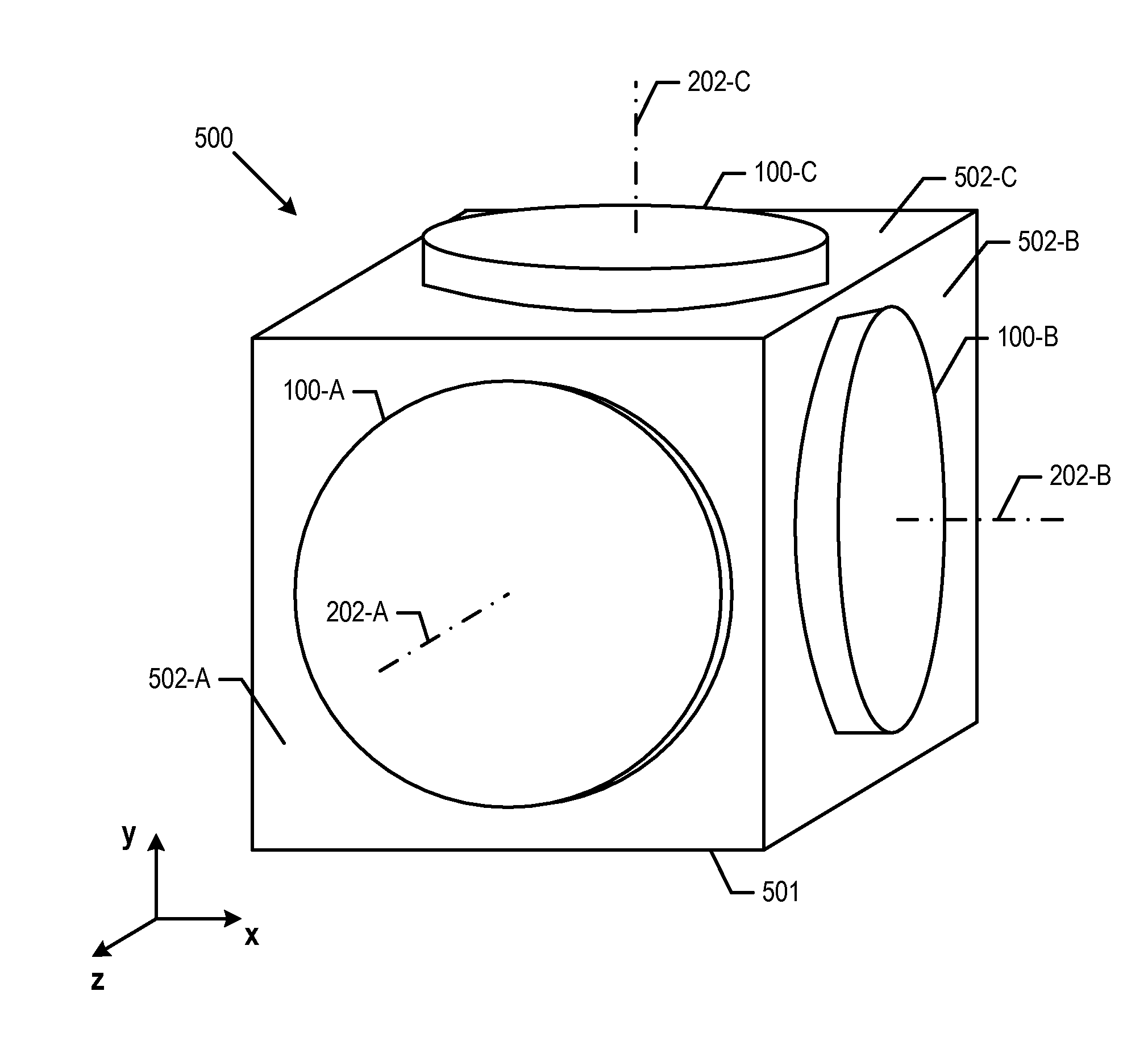
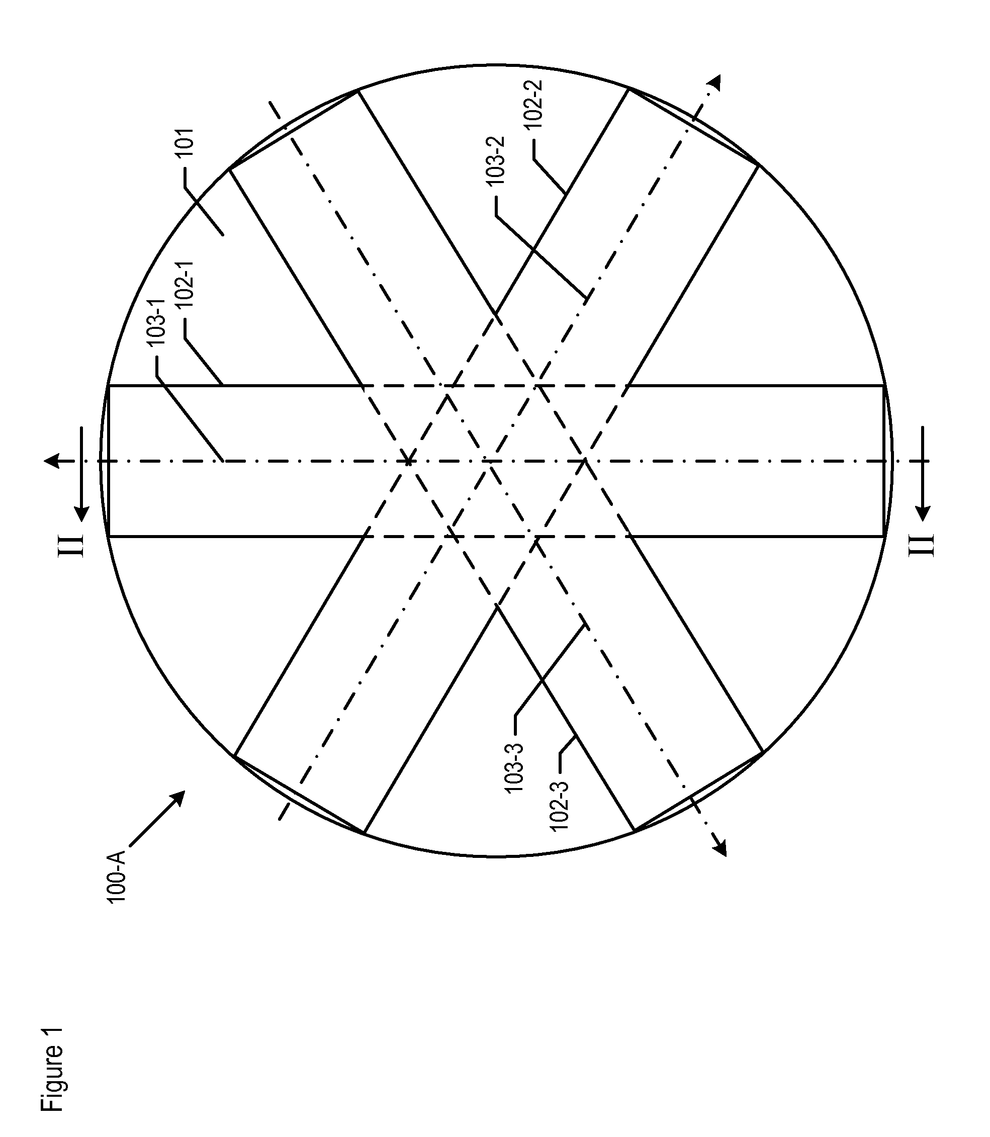
[0022]FIG. 1 depicts a top-plan view of gravity gradiometer 100-A, in accordance with the illustrative embodiment of the present invention. Gradiometers 100-A comprises base 101, which is an object to which multiple accelerometer pairs are attached. Although for purposes of clarity base 101 is depicted as a disc-shaped plate, the base can be shaped differently than depicted, as those who are skilled in the art will appreciate.

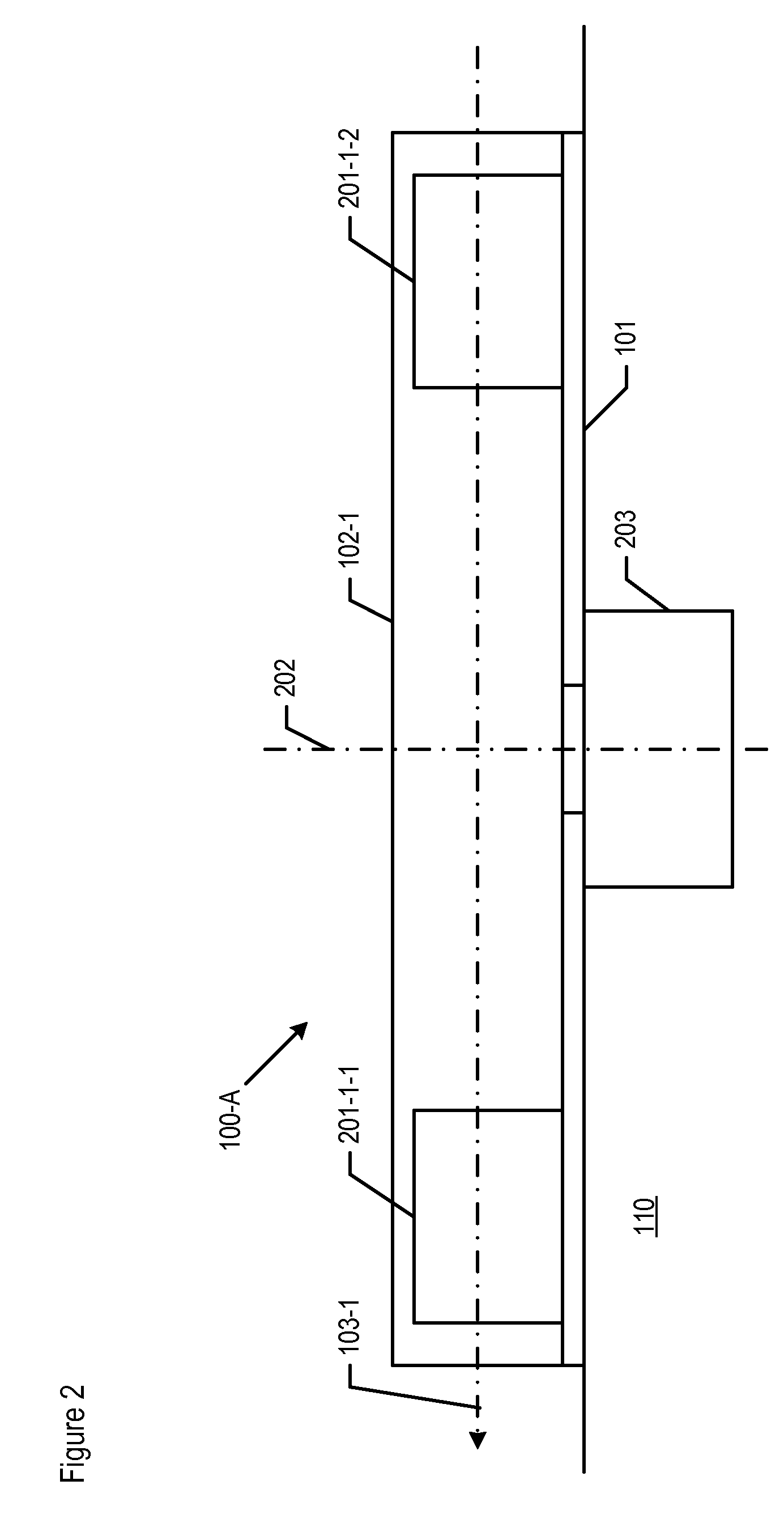
[0023]Gradiometer 100-A further comprises accelerometer pairs 102-1, 102-2, and 102-3 mounted upon base 101. Accelerometer pairs 102-1 through 102-3 are described in detail below and with respect to FIGS. 2 through 4. As shown in FIG. 1, each accelerometer pair 102-1 through 102-3 is capable of measuring a gravity gradient along measuring axis 103-1 through 103-3, respectively. Measuring axes 103-1 through 103-3 are oriented such that the measuring directions are spaced 120 degrees apart from one another.

[0024]Three accelerometer pairs are depicted in FIG. 1, i...


PUM


Abstract

A full-tensor, gravity gradient measuring system is disclosed that is based on atom interferometry. Each axis in the three-axis measuring system is served by a different gravity gradiometer, where each gradiometer comprises three pairs of atom interferometric (AI) accelerometers. The accelerometers in each pair are mounted on opposite sides of the gradiometer's rotation axis from each other. The three AI accelerometer pairs are step-rotated, instead of being continuously rotated, thereby providing enhanced signal-to-noise performance. The three gradiometers in the overall measuring system are mounted orthogonally with respect to one another on a local-level platform, in order to achieve a full-tensor measuring system. The measuring system can be step-rotated as an overall unit around an axis perpendicular to a local level reference. The multiple levels of stepped rotation, as enabled by the atom interferometry being utilized, yields improved results with lower costs than what is achievable with some prior-art techniques.

Description

FIELD OF THE INVENTION[0001]The present invention relates to gravity gradiometers in general, and, more particularly, to a stepped gravity gradiometer system based on atom interferometry.BACKGROUND OF THE INVENTION[0002]Devices that can sense departures of their own reference frame from an “inertial reference frame” are of important practical and commercial use—for example, in the area of inertial navigation and guidance. A gravity gradiometer is one such device, which is used to measure the gradient of a gravitational field.[0003]Some gradiometers in the prior art utilize a main sensing element. This sensing element is a metallic sphere with high-density weights located at opposite ends of a diameter. The sensing sphere or float is symmetric about this diameter. It is suspended both electrostatically and by a fluid within a hollow sphere, and is free to rotate inside. When a given mass is passed by the device, the mass pulls more on the nearer weight than on the farther. A torque i...

Claims


Application Information

Patent Timeline
Patent Type & Authority Patents(United States)
IPC IPC(8): G01V7/00
CPCG01P15/08G01P15/18G01V7/00
Inventor RICE, HUGH F.LINDELL, JACK C.DIFRANCESCO, DANIEL J.
Owner LOCKHEED MARTIN CORP
Why Eureka
Try Eureka