Self-drilling screw and fabricating method for the same

a self-drilling screw and fabricating method technology, applied in the direction of screw threads, screws, screw-thread articles, etc., can solve the problems of increasing the cost of punching dies, self-drilling screws, stainless steel fabrication difficulties, etc., to reduce the size of punching dies, reduce the load of punching machines, and reduce the effect of punching for

Inactive Publication Date: 2013-01-08
LAI TSUNG CHENG
View PDF4 Cites 4 Cited by
  • Summary
  • Abstract
  • Description
  • Claims
  • Application Information

AI Technical Summary

Benefits of technology

[0009]The main objective of the present invention is to provide a self-drilling screw that reduces the size of the punching die, lowers the punching force, lowers both the load of the punching die and the load of the punching machine, lowers both the die cost and the manufacturing cost, and is beneficial for the removal of chips.
[0011]Another objective of the present invention is to provide a fabricating method for a self-drilling screw that reduces the size of the punching die, lowers the punching force, lowers both the load of the punching die and the load of the punching machine, lowers both the die cost and the manufacturing cost, and is beneficial for the removal of chips.
[0016]The present invention utilizes the flat drilling blade with the tapered end and the chip removal section having chip removal function to reduce the size of the drilling blade. Therefore, the present invention reduces the size of the punching die, lowers the punching force, lowers both the load of the punching die and the load of the punching machine, improves the quality of the self-drilling screw, and lowers both the die cost and the manufacturing cost. Besides, the present invention is especially suitable for fabricating the self-drilling screw of big size and made from material hard to manufacture like stainless steel.

Problems solved by technology

However, because the size of self-drilling screws is larger or the material of self-drilling screws is harder, self-drilling screws having international standard number larger than No. 5, having diameter larger than 6.5 mm, or made from stainless steel are difficult to fabricate by punching.
The size of the punching die is larger while the length or width of the drilling blade is larger, which increases the cost of the punching die.
Besides, the punching machine must output larger punching force while the size of the punching die is larger or the blank is more difficult to form, which increases both the load of the punching die and the load of the punching machine.
Moreover, larger punching force damages the punching die easier, which also increases manufacturing cost.
Because of the limitation of the punching, the chip removal groove is not spiral and is almost parallel to an axial direction of the self-drilling screw, which is bad for the removal of the chips.

Method used


Image

  • Self-drilling screw and fabricating method for the same
  • Self-drilling screw and fabricating method for the same
  • Self-drilling screw and fabricating method for the same

Examples


Embodiment Construction

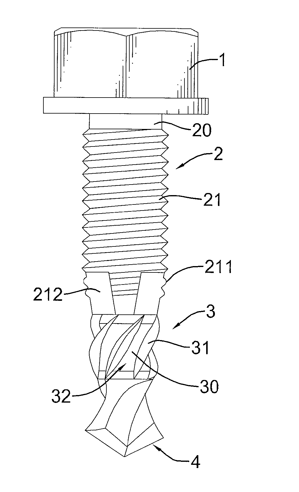
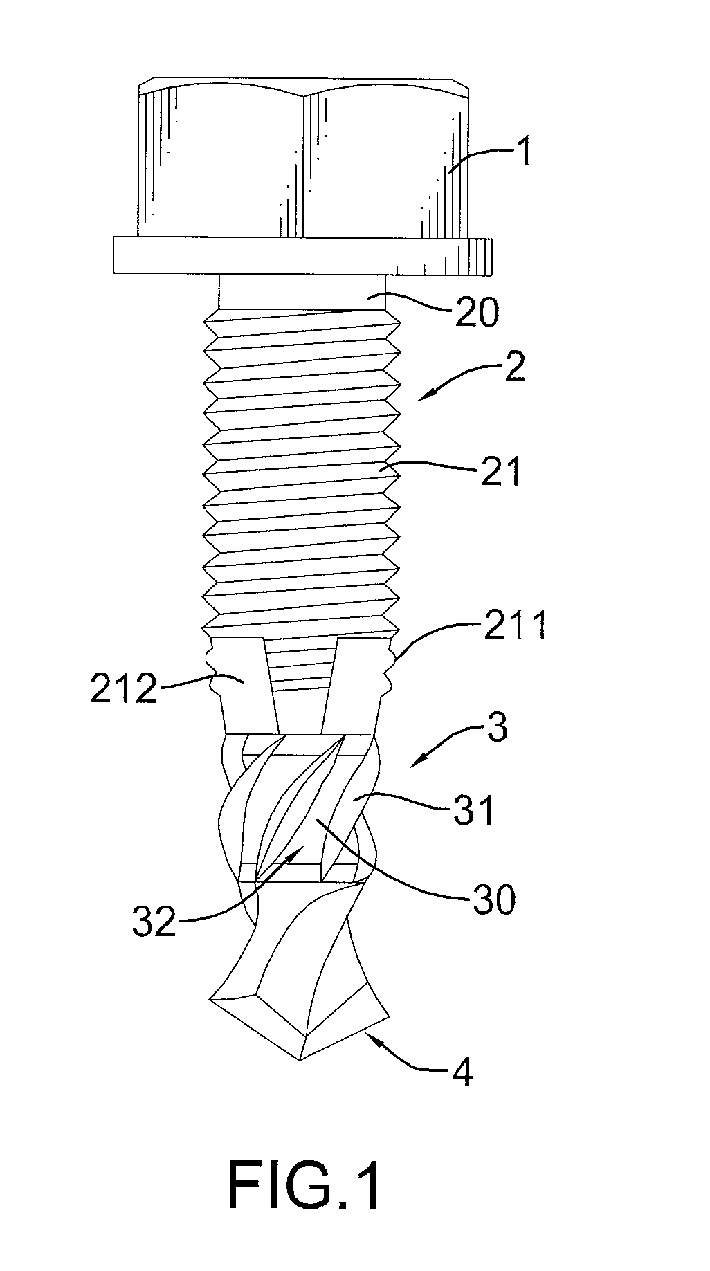
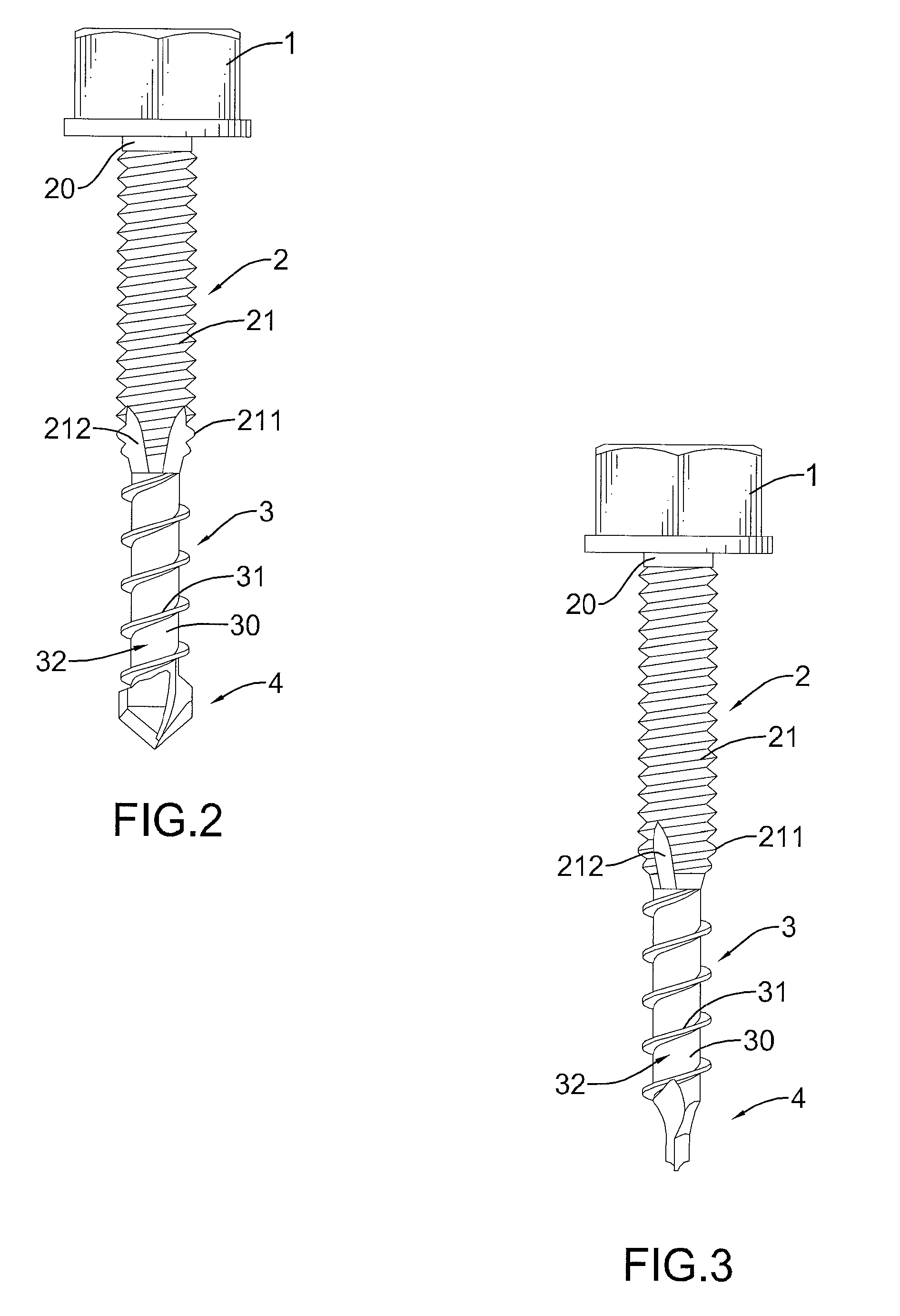
[0026]With reference to FIGS. 1 and 2, a self-drilling screw in accordance with the present invention comprises a screw head 1, a body 2, a chip removal section 3 and a drilling blade 4.

[0027]The screw head 1 may be a hemisphere, hexagon or flat-topped cone. When the screw head 1 is hexagonal or a flat-topped cone, a top surface of the screw head 1 may have a hexagon hole or a cross slot for a tool to engage.

[0028]The body 2 is formed on a bottom end of the screw head 1. The body 2 has a screw rod 20 and a thread portion 21. The screw rod 20 protrudes longitudinally from the bottom end of the screw head 1. The thread portion 21 is formed on an outer surface of the screw rod 20.

[0029]The chip removal section 3 is formed on a bottom end of the body 2 and has a chip removal rod 30, a chip removal thread portion 31 and a spiral chip removal groove 32. The chip removal rod 30 protrudes longitudinally from the bottom end of the screw rod 20. The chip removal rod 30 is thinner than the scr...


PUM

PropertyMeasurementUnit
diameteraaaaaaaaaa
outer diameteraaaaaaaaaa
diameteraaaaaaaaaa

Abstract

A fabricating method for the self-drilling screw has acts of forming a main section and a secondary section by punching, forming a flat drilling blade with a tapered end at a bottom end of the small diameter portion by punching, and forming a thread portion on an outer surface of the main section and a chip removal thread portion with a spiral chip removal groove on an outer surface of the secondary section by rolling. The self-drilling screw utilizes the flat drilling blade with the tapered end and the chip removal section having chip removal function to reduce the size of the drilling blade. Therefore, the self-drilling screw reduces the size of the punching die, lowers the punching force, lowers both the load of the punching die and the load of the punching machine, and lowers both the die cost and the manufacturing cost.

Description

BACKGROUND OF THE INVENTION[0001]1. Field of the Invention[0002]The present invention relates to a self-drilling screw, especially to a self-drilling screw which can lower die cost.[0003]2. Description of the Prior Arts[0004]With reference to FIG. 6, a conventional self-drilling screw has a screw head 51 and a rod-shaped main body 50. The main body 50 has a thread portion 52 and a drilling blade 53. The thread portion 52 is formed around the main body 50. The drilling blade 53 is formed on an end of the main body 50. By the design of the drilling blade 53 of the conventional self-drilling screw, the conventional self-drilling screw has drilling, tapping and fastening functions.[0005]With reference to FIGS. 7A to 7C, a conventional fabricating method for the conventional self-drilling screw has following steps: forming a screw blank B which has a screw head 51 and a rod B1 by punching, forming a rod-shaped drilling blade 53 at an end of the rod B1 of the screw blank B by punching, an...

Claims


Application Information

Patent Timeline
Patent Type & Authority Patents(United States)
IPC IPC(8): F16B25/10
CPCB21H3/027F16B25/0057F16B25/103
Inventor LAI, TSUNG-CHENG
Owner LAI TSUNG CHENG
Why Eureka
Try Eureka