Method and system for providing a magnetoresistive structure using undercut free mask

a magnetoresistive structure and mask technology, applied in the field of providing a magnetoresistive structure using undercut free mask, can solve the problems of difficult removal, higher densities, and general undesirable variations, and achieve the effect of masks, and reducing the number of masks

Inactive Publication Date: 2013-01-08
WESTERN DIGITAL TECH INC
View PDF55 Cites 152 Cited by
  • Summary
  • Abstract
  • Description
  • Claims
  • Application Information

AI Technical Summary

Benefits of technology

[0008]FIG. 1 depicts a conventional method for fabricating a magnetoresistive dev

Problems solved by technology

Although the conventional method 10 functions at lower densities, issues arise for higher densities.
Such variations

Method used


Image

  • Method and system for providing a magnetoresistive structure using undercut free mask
  • Method and system for providing a magnetoresistive structure using undercut free mask
  • Method and system for providing a magnetoresistive structure using undercut free mask

Examples


Embodiment Construction

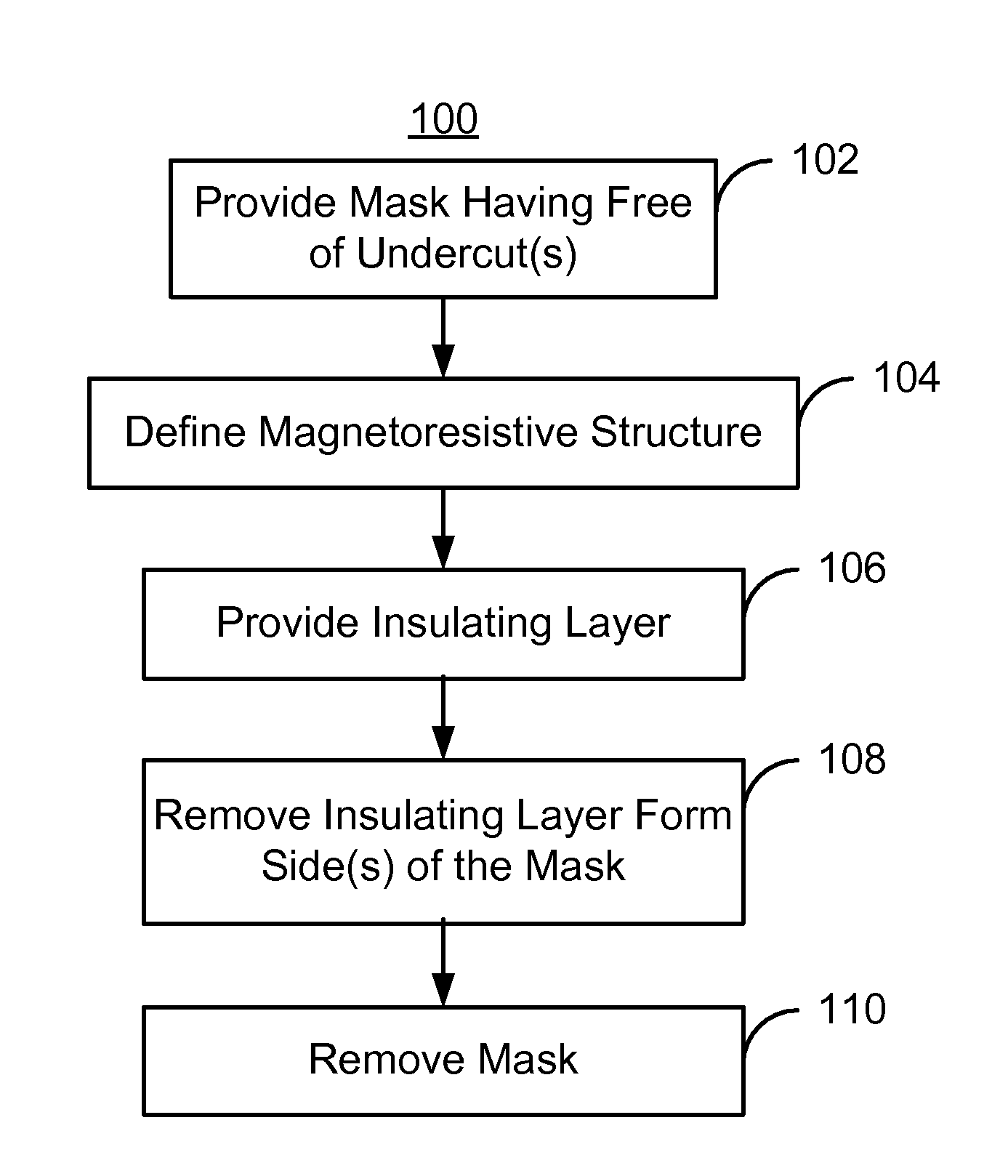
[0013]FIG. 4 is a flow chart depicting an exemplary embodiment of a method 100 for defining a magnetoresistive structure from a magnetoresistive stack. Although the method 100 is described in the context of particular steps and particular magnetoresistive elements, other magnetoresistive elements may be provided and different and / or additional steps may be used. The steps described may also include one or more sub-steps. In addition, although the method 100 is described in the context of single layers, in one embodiment, such a layer may include multiple layers. The method 100 is also described in the context of providing a single magnetoresistive structure in a magnetic device. However, the method 100 may be used to fabricate multiple magnetoresistive structures and / or multiple magnetic devices at substantially the same time. The method 100 is also described in the context of defining the stripe height for the magnetoresistive structure. Consequently, discussion of structures such ...


PUM

PropertyMeasurementUnit
Pressureaaaaaaaaaa
Angleaaaaaaaaaa
Angleaaaaaaaaaa

Abstract

A method and system provide a magnetoresistive structure from a magnetoresistive stack that includes a plurality of layers. The method and system include providing a mask that exposes a portion of the magnetoresistive stack. The mask has at least one side, a top, and a base at least as wide as the top. The method and system also include removing the portion of the magnetoresistive stack to define the magnetoresistive structure. The method and system further include providing an insulating layer. A portion of the insulating layer resides on the at least one side of the mask. The method and system further include removing the portion of the insulating layer on the at least one side of the mask and removing the mask.

Description

BACKGROUND[0001]FIG. 1 depicts a conventional method 10 for defining the stripe height of a magnetoresistive structure using a conventional undercut bi-layer mask. FIGS. 2-3 depict a conventional magnetoresistive device 50, such as a read transducer, during fabrication using the conventional method 10. Referring to FIGS. 1-3, the layers of the magnetoresistive structure stack are provided, via step 12. Typically, step 12 includes sputtering or otherwise depositing the layers for a spin valve or other analogous giant magnetoresistive (GMR) element. A bi-layer mask is provided on the device, via step 14. FIG. 2 depicts a side view of the conventional transducer 50 after step 14 is performed. Thus, the conventional transducer 50 includes a magnetoresistive stack 54 of the magnetoresistive structure layers formed on a substrate 52, which is typically a shield. On the magnetoresistive stack 54 is a bi-layer mask 56 that includes a polydimethylglutarimide (PMGI) layer 60 and a photoresist...

Claims


Application Information

Patent Timeline
IPC IPC(8): B44C1/22G11B5/127
CPCG11B5/3912G11B5/3163B82Y10/00G11B5/398G11B2005/3996Y10T29/49052Y10T29/49046Y10T29/49043
Inventor SI, WEIMINHONG, LIUBOZHU, HONGLINYU, WINNIESCHMIDT, ROWENA
Owner WESTERN DIGITAL TECH INC
Why Eureka
Try Eureka