Dynamoelectric machine

Inactive Publication Date: 2013-01-08
SIEMENS AG
View PDF17 Cites 3 Cited by
  • Summary
  • Abstract
  • Description
  • Claims
  • Application Information

AI Technical Summary

Benefits of technology

The patent describes a cooling system for a closed dynamoelectric machine using heat pipes. The heat pipes are arranged in a radial manner on the end sides of the stator, providing protection against damage to the machine. The heat pipes absorb and transport heat from the rotor and stator components, reducing the temperature difference between the inside and outside of the machine. To improve cooling performance, the number of heat pipes can be increased, and a mesh can be added to increase the surface area of the evaporation and condensation zones, improving heat absorption and transfer. Additionally, axial recesses in the rotor allow for a uniform temperature and further enhance cooling efficiency. Overall, the cooling system provides improved protection and performance for closed dynamoelectric machines.

Problems solved by technology

These losses in dynamoelectric machines arise in particular from iron losses and eddy current losses.
In closed dynamoelectric machines with air cooling, the factor that limits efficiency is often the heating of the rotor.

Method used


Image

  • Dynamoelectric machine
  • Dynamoelectric machine
  • Dynamoelectric machine

Examples


Embodiment Construction

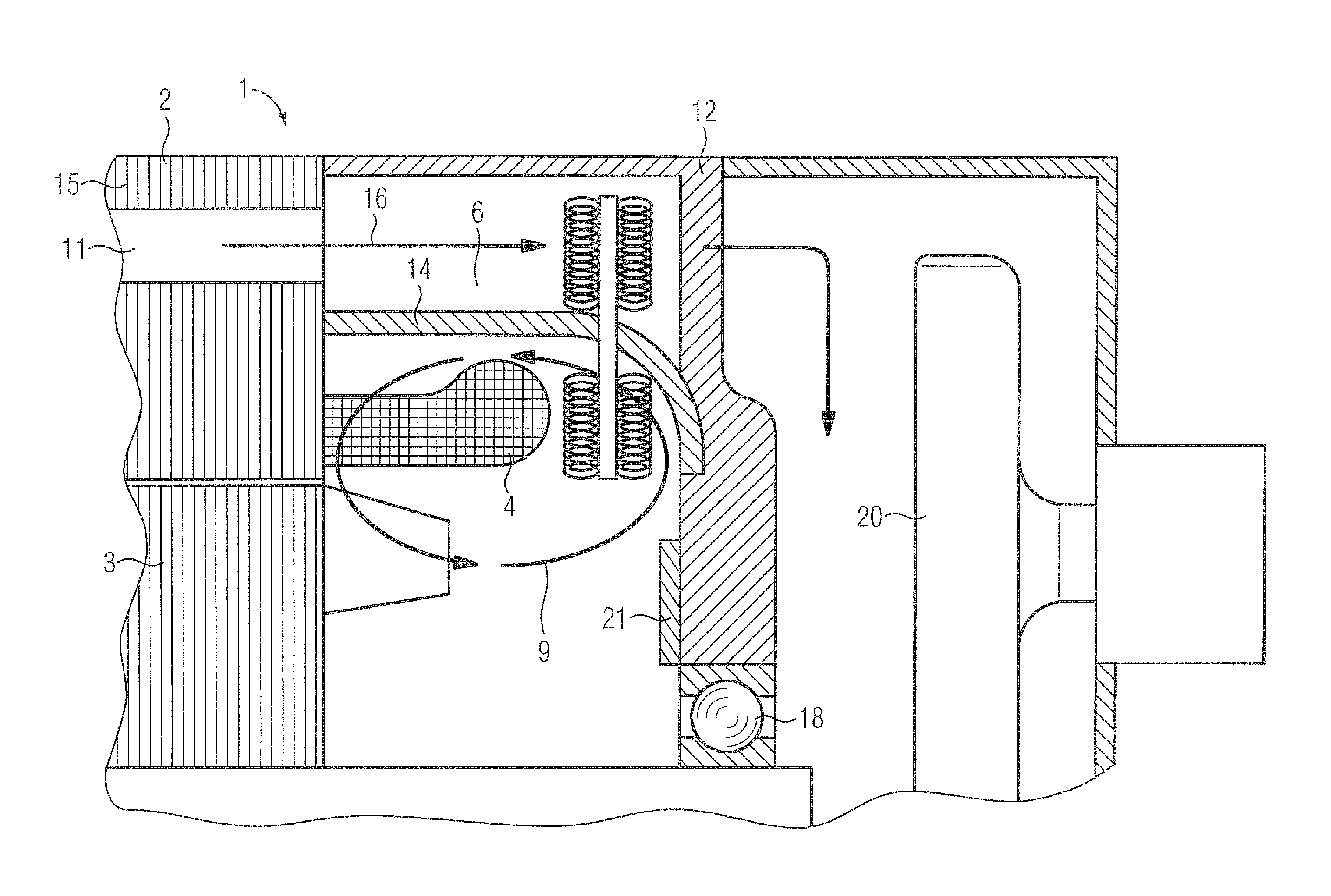
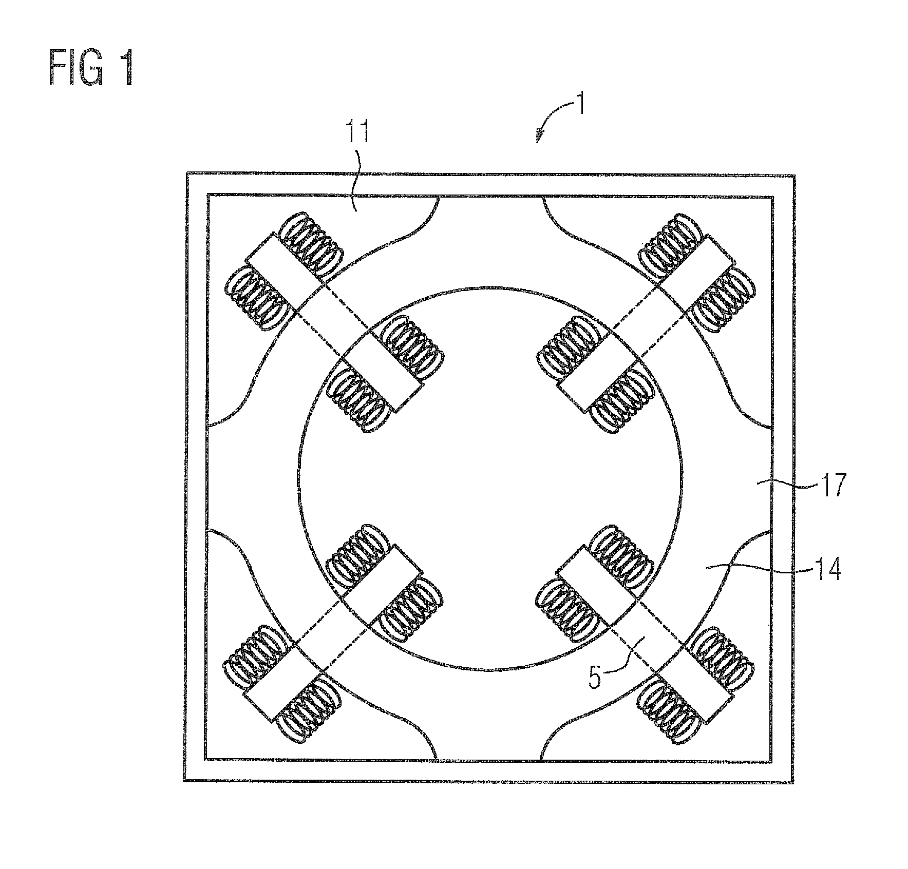
[0029]FIG. 1 shows in a basic cross section a dynamoelectric machine 1 comprising a housing against which a protective pipe 14 is supported via supports 17. For the sake of clarity, neither the winding system 4 nor the rotor 3 have been shown in this FIG.

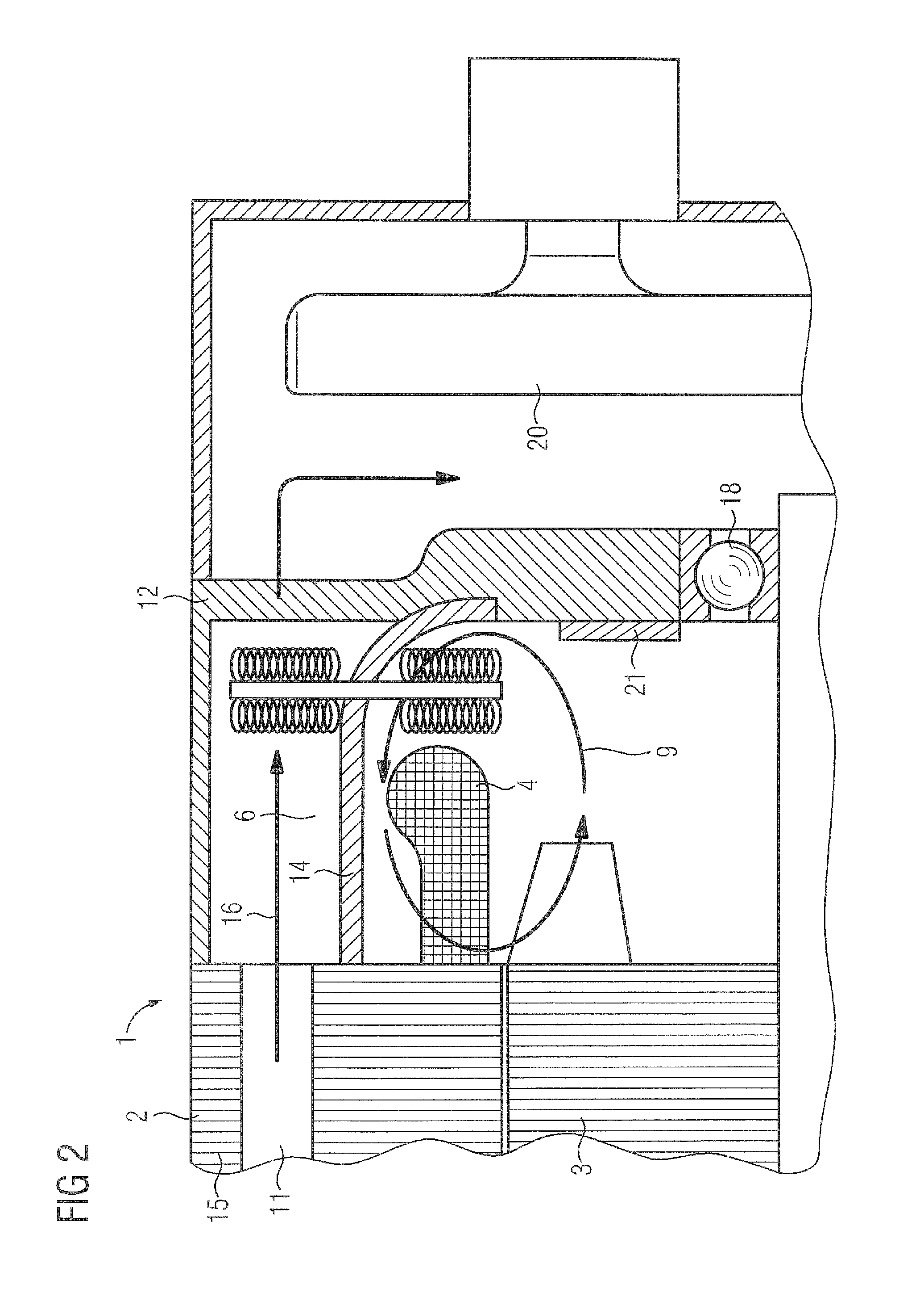
[0030]The protective pipe 14 surrounds, as can also be seen clearly in FIG. 2, the electrically sensitive parts such as, for example, the winding system 4 with its end windings as well as the rotor 3 which rotates. The heat from the rotor 3 and the winding system 4 must now be conveyed to the outside via the protective pipe 14. This happens according to the invention by heat pipes 5, in this case four heat pipes 5, being arranged radially in the corners of the housing and having meshes 8 both in the end portions of the evaporation zones 19 of the heat pipes 5 and in the end portions of the condensation zones 7. These meshes 8 enlarge the heat absorption or transmission surface area and moreover ensure that the flow of air surroundin...


PUM


Abstract

The invention relates to a dynamoelectric machine (1) comprising a stator (2) and a rotor (3). At least the stator (2) has a winding system (4) which is arranged in grooves of the stator (2). Heat is transferred in a substantially radial direction on the front sides (6) of the stator (2) by means of heat pipes (5).

Description

CROSS-REFERENCES TO RELATED APPLICATIONS[0001]This application is the U.S. National Stage of International Application No. PCT / EP2009 / 061841, filed Sep. 14, 2009, which designated the United States and has been published as International Publication No. WO 2010 / 046182 A2 and which claims the priority of German Patent Application, Serial No. 10 2008 053 090.5, filed Oct. 24, 2008, pursuant to 35 U.S.C. 119(a)-(d).BACKGROUND OF THE INVENTION[0002]The invention relates to a dynamoelectric machine comprising a stator and a rotor, the stator having a winding system arranged in grooves of the stator, and the cooling system having heat pipes.[0003]Dynamoelectric machines are equipped with an air or fluid cooling system in order to remove the losses of heat from lamination stacks of the stator and / or lamination stacks of the rotor as well as from the winding systems. These losses in dynamoelectric machines arise in particular from iron losses and eddy current losses. In order now to further...

Claims


Application Information

Patent Timeline
IPC IPC(8): H02K9/20
CPCF28D15/0275F28F1/122H02K9/20H02K9/225
Inventor AF URSIN, ILKKA
Owner SIEMENS AG
Why Eureka
Try Eureka