System for controlling input profiles of combined cycle power generation system

a power generation system and input profile technology, applied in adaptive control, process and machine control, instruments, etc., can solve the problems of reducing the availability increasing fuel costs, and not always clear best choice from such options, so as to improve the startup conditions of the power generation system and improve the operation of the combined cycle power generation system.

Active Publication Date: 2013-01-08
GENERAL ELECTRIC CO +1
View PDF27 Cites 19 Cited by
  • Summary
  • Abstract
  • Description
  • Claims
  • Application Information

AI Technical Summary

Problems solved by technology

However, the best choice from such options is not always clear.
If the GT loading rates are very high, large thermal gradients may be developed in the ST, leading to high stresses and uneven thermal expansion that could result in rubs.
Conversely, slow GT loading rates ensure a safe operation but increase fuel costs and reduce power generation system availability.
One challenge in generating optimal power plant control actions during transient operation is dissimilar time scales of dynamics of different components.
However, slowly blending the lag steam into the ST may result in unnecessary delays to complete the blending.
Control guidance to trigger the event is typically conservative in the sense that unnecessarily long delays may be introduced before the event is allowed.

Method used


Image

  • System for controlling input profiles of combined cycle power generation system
  • System for controlling input profiles of combined cycle power generation system
  • System for controlling input profiles of combined cycle power generation system

Examples


Embodiment Construction

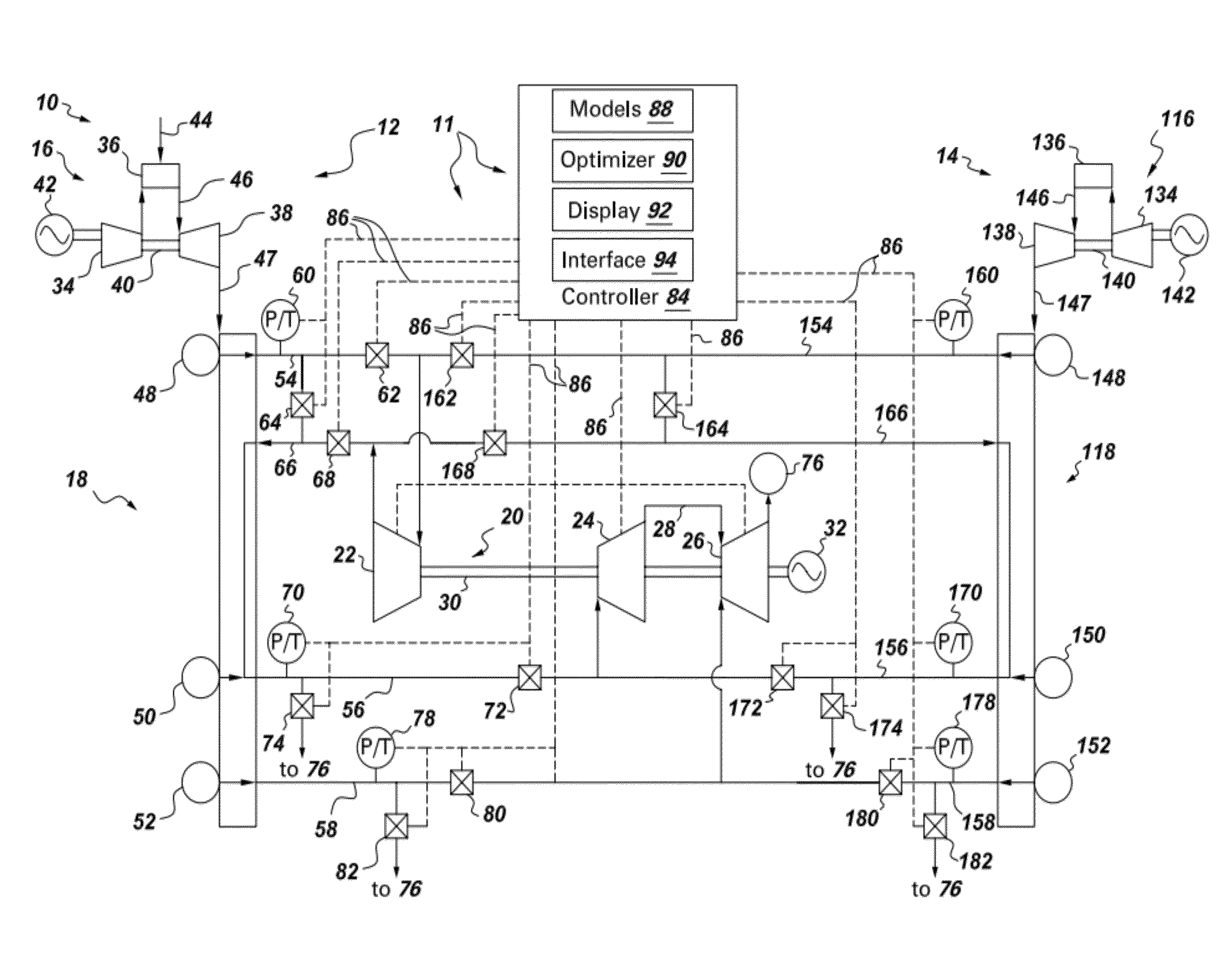
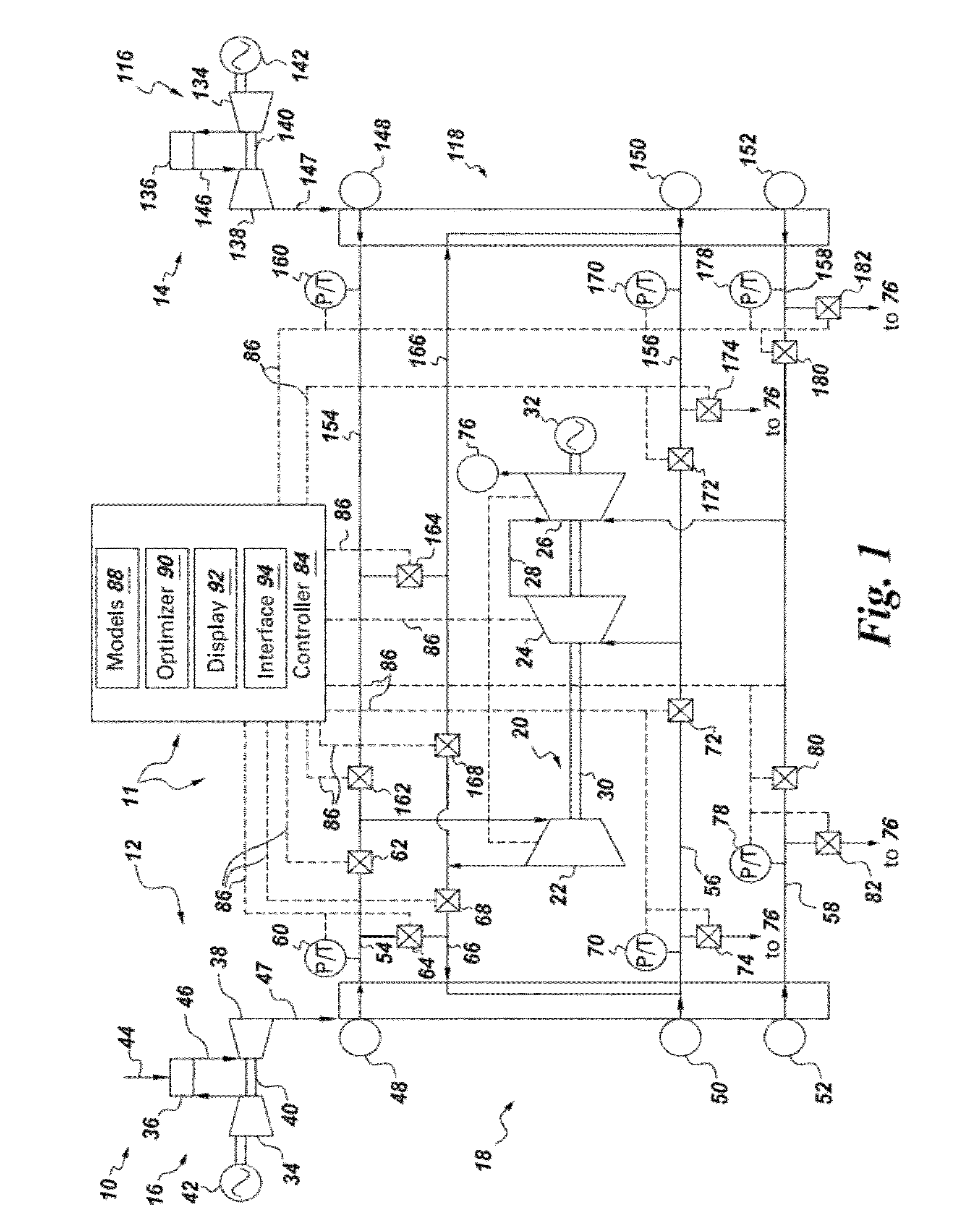
[0017]FIG. 1 is a schematic diagram of an exemplary combined-cycle power generation system 10. Generally, system 10 includes a lead side 12 and a lag side 14. Lead side 12 includes a gas turbine engine (GT) 16 that is coupled in flow communication with a heat recovery steam generator (HRSG) 18. HRSG 18 is coupled in flow communication with a steam turbine assembly (ST) 20. ST 20 includes a high pressure (HP) turbine 22, an intermediate pressure (IP) turbine 24, and a low pressure (LP) turbine 26. IP turbine 24 is coupled in flow communication to LP turbine 26 using an IP-to-LP crossover header 28. Turbines 22, 24, and 26 are each coupled to a rotor shaft 30 that is also coupled to an electric generator 32.

[0018]In the embodiment of FIG. 1, lead GT 16 includes a compressor 34, a combustor 36, and a turbine 38. Compressor 34 is coupled in flow communication with combustor 36, which is coupled in flow communication upstream from turbine 38. Compressor 34 and turbine 38 are each coupled...


PUM


Abstract

A control system for a combined cycle power generation system including a gas turbine engine (GT), a heat recovery steam generator (HRSG), and a steam turbine (ST) includes a display wherein an operator may observe information about predicted operating parameters; a user interface wherein an operator may provide additional operating constraints; and a controller configured to generate input profiles of the GT, the HRSG, and the ST that satisfy the nominal constraints and any additional constraints and to generate the information about the predicted operating parameters. The controller may be configured to detect a stage transition of power generation system operation and update the input profiles. The controller may be configured to generate alternative operating scenarios by mapping alternative control actions to an operating constraint of at least one of the system components.

Description

BACKGROUND[0001]The subject matter disclosed herein relates generally to combined-cycle (CC) power generation systems.[0002]Increased cyclic duty requirements, higher fuel costs, competitive deregulated energy markets, and stringent environmental regulations are resulting in a demand for faster sequences from CC power generation system operations. Furthermore, power generation system owners manage different startup objectives depending on local environmental regulations, energy dispatch requirements, and current fuel and energy prices. A typical startup objective is the reduction of startup time. However, the power generation system operator may need to minimize emissions, fuel costs, or net heat rate. Additional flexibility is also useful due to some startup procedures occurring over several hours and the potential for load, market, or power system conditions to change during that time period.[0003]Commonly assigned US20070055392, filed 6 Sep. 2005, which is herein incorporated by ...

Claims


Application Information

Patent Timeline
Patent Type & Authority Patents(United States)
IPC IPC(8): G06F19/00
CPCG05B13/048Y02E20/16F01K27/00F02C9/00F02C9/28G05B13/02
Inventor D'AMATO, FERNANDO JAVIERKIRCHHOF, DARRIN GLENBAKER, DEAN ALEXANDERCHANDRA, RAMU SHARATHOLZHAUER, DANIEL FRANCISLONG, CHRISTOPHER EUGENE
Owner GENERAL ELECTRIC CO
Why Eureka
Try Eureka