Method of detecting system function by measuring frequency response

a technology of frequency response and system function, applied in the direction of pulse characteristics measurement, instruments, testing circuits, etc., can solve the problems of time-consuming and expensive laboratory equipment, and achieve the effect of reducing time-consuming summation transformation

Active Publication Date: 2013-01-08
BATTELLE ENERGY ALLIANCE LLC
View PDF28 Cites 26 Cited by
  • Summary
  • Abstract
  • Description
  • Claims
  • Application Information

AI Technical Summary

Problems solved by technology

This method is effective in assessing ESD degradation over time and usage, but it requires expensive laboratory equipment, and it can be time consuming given the serial measurement approach.
However, this approach requires the average of multiple measurements to adequately determine the impedance response over the desired frequency range, which also makes it more of a serial approach.

Method used


Image

  • Method of detecting system function by measuring frequency response
  • Method of detecting system function by measuring frequency response
  • Method of detecting system function by measuring frequency response

Examples


Embodiment Construction

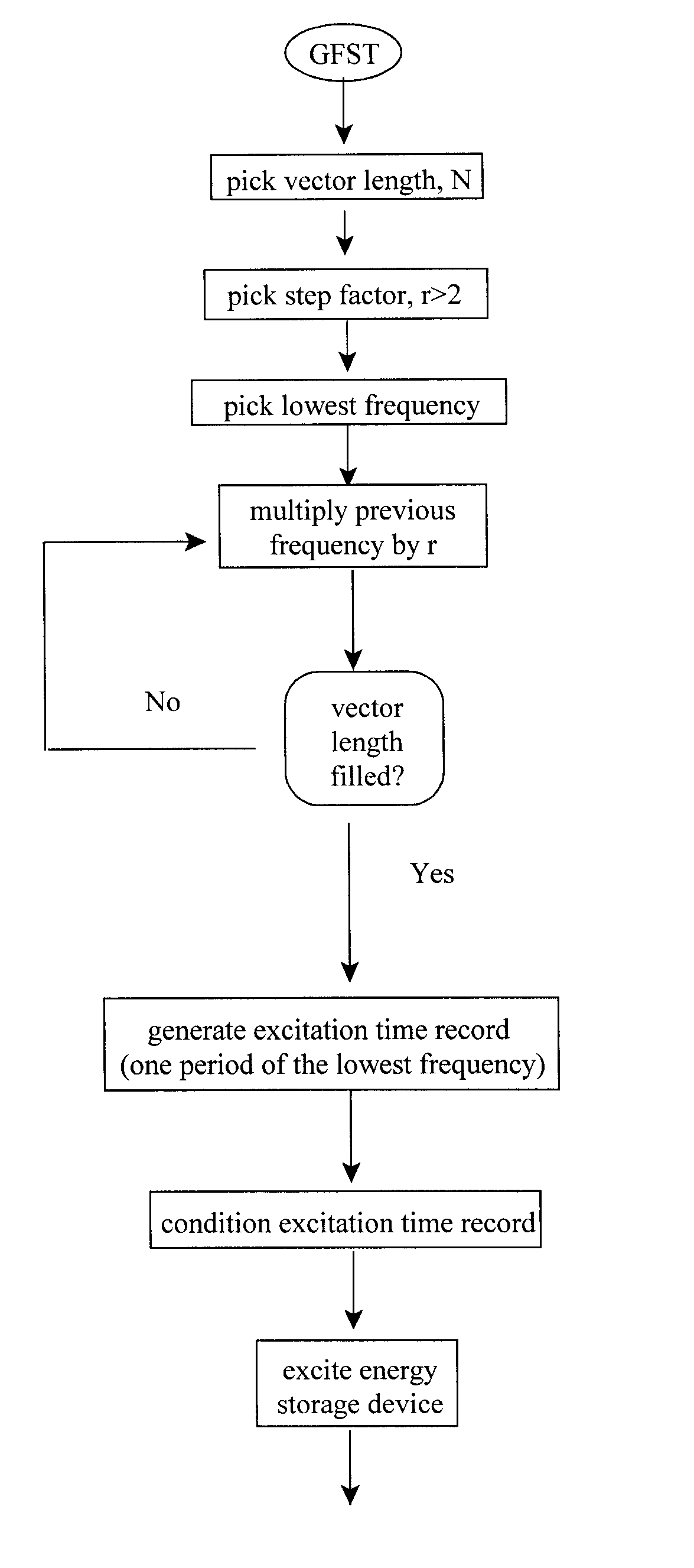
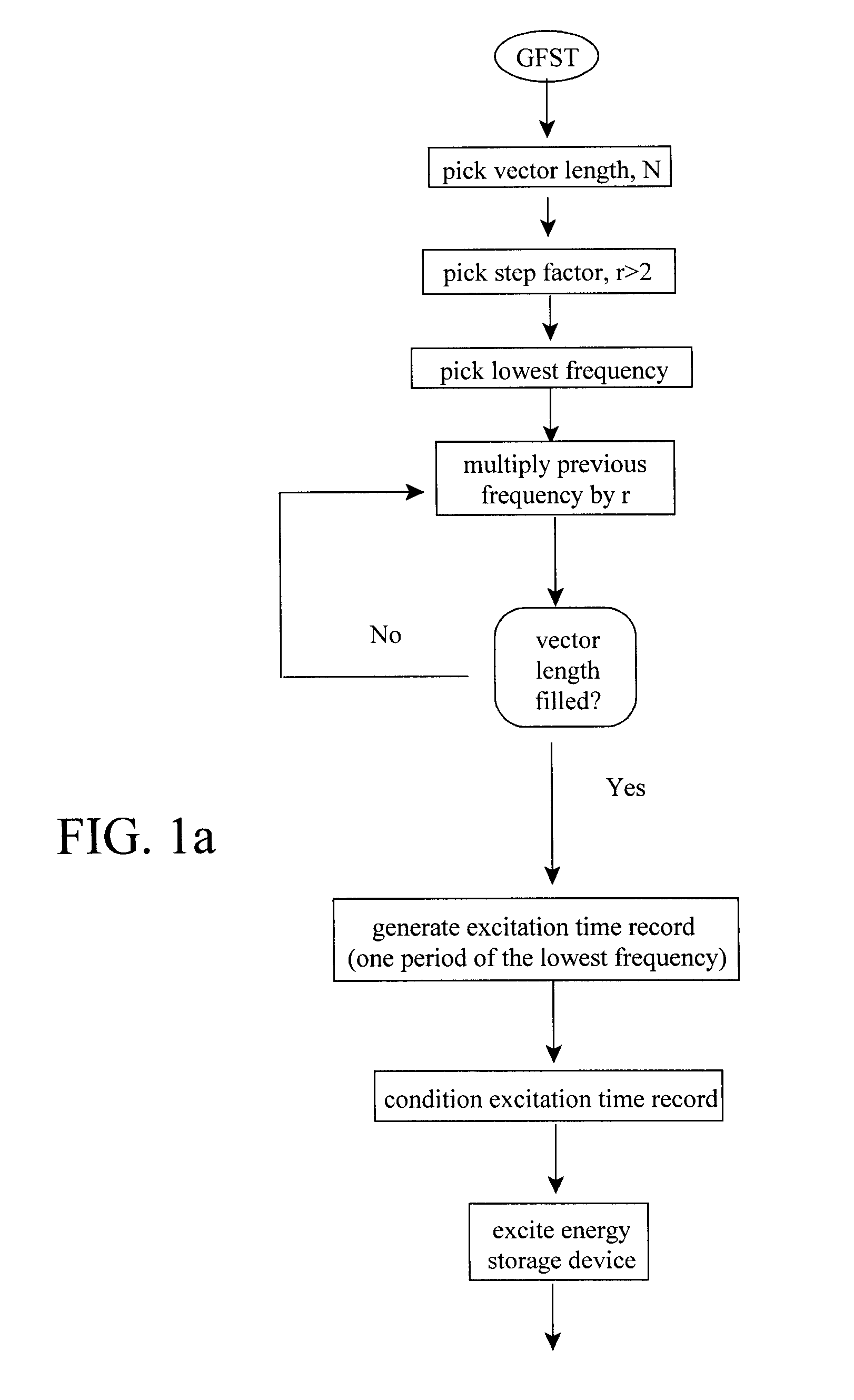
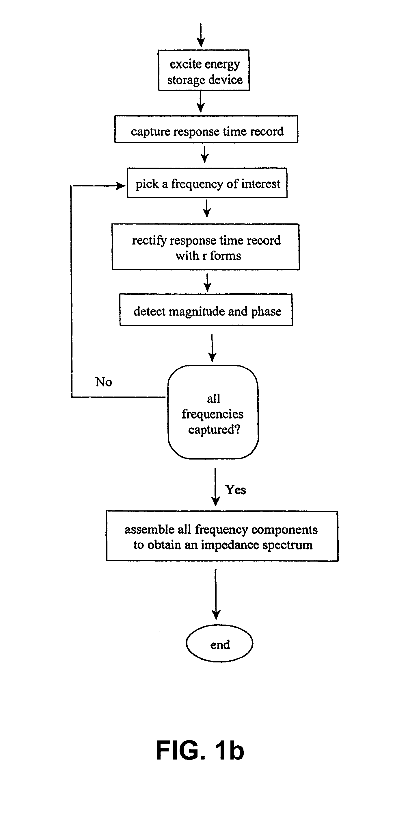
[0013]A method of the subject invention allows for rapid measurement of the impedance for energy storage devices. It has been shown that shifts in the impedance spectra, as a function of time and use, strongly correlate to the health of, for example, battery technologies (Christophersen et al., “Electrochemical Impedance Spectroscopy Testing on the Advanced Technology Development Program Lithium-Ion Cells,”IEEE Trans. Veh. Technol., 56(3). 1851-1855, 2002). Therefore, the subject method provides information about energy storage devices that is critical for onboard diagnostics and state-of-health estimation. The subject method measures a frequency response of an ESD (e.g., a battery) by exciting it with an SOS signal consisting of a number of select frequencies, and then capturing a response time record. The data are processed to obtain the impedance at each frequency in interest.

[0014]The desired frequencies are assembled as an excitation time record that can consist of a sum-of-sin...


PUM


Abstract

Methods of rapidly measuring an impedance spectrum of an energy storage device in-situ over a limited number of logarithmically distributed frequencies are described. An energy storage device is excited with a known input signal, and a response is measured to ascertain the impedance spectrum. An excitation signal is a limited time duration sum-of-sines consisting of a select number of frequencies. In one embodiment, magnitude and phase of each frequency of interest within the sum-of-sines is identified when the selected frequencies and sample rate are logarithmic integer steps greater than two. This technique requires a measurement with a duration of one period of the lowest frequency. In another embodiment, where selected frequencies are distributed in octave steps, the impedance spectrum can be determined using a captured time record that is reduced to a half-period of the lowest frequency.

Description

CROSS-REFERENCE TO RELATED APPLICATIONS[0001]This application is a continuation-in-part of U.S. patent application Ser. No. 12 / 217,013, filed Jun. 30, 2008, now U.S. Pat. No. 8,150,643, issued Apr. 3, 2012, which is a continuation-in-part of U.S. patent application Ser. No. 11 / 825,629, filed Jul. 5, 2007, now U.S. Pat. No. 7,395,163, issued Jul. 1, 2008, which is a continuation of U.S. patent application Ser. No. 11 / 313,546, filed Dec. 20, 2005, now abandoned, which claims the benefit of U.S. Provisional Patent Application Nos. 60 / 637,969, filed Dec. 20, 2004, and 60 / 724,631, filed Oct. 7, 2005. This application further claims the benefit of U.S. Provisional Patent Application No. 61 / 186,358, filed Jun. 11, 2009. The disclosure of each of these applications are hereby incorporated herein by reference in their entirety, including all figures, tables and drawings.STATEMENT REGARDING FEDERALLY SPONSORED RESEARCH OR DEVELOPMENT[0002]This invention was made with government support under ...

Claims


Application Information

Patent Timeline
Patent Type & Authority Patents(United States)
IPC IPC(8): G01R23/00G01R27/28G01R31/00
CPCG01R31/2837
Inventor MORRISON, JOHN L.MORRISON, WILLIAM H.CHRISTOPHERSEN, JON P.MOTLOCH, CHESTER G.
Owner BATTELLE ENERGY ALLIANCE LLC
Why Eureka
Try Eureka