Method of Detecting System Function by Measuring Frequency Response

a technology of frequency response and system function, applied in the direction of pulse characteristics measurement, instruments, testing circuits, etc., can solve the problems of time-consuming and expensive laboratory equipmen

Active Publication Date: 2010-10-28
BATTELLE ENERGY ALLIANCE LLC
View PDF27 Cites 30 Cited by
  • Summary
  • Abstract
  • Description
  • Claims
  • Application Information

AI Technical Summary

Benefits of technology

[0010]In one preferred embodiment, Generalized Fast Summation Transformation (GFST), the test frequencies included in the SOS signal are increased by an integer greater than two (i.e., N>2, whereas FST is based on N=2). A start frequency is chosen and multiplied by the integer step factor to get the next test frequency, and this process is repeated until the desired frequency range is covered. The resulting test frequen

Problems solved by technology

This method is effective in assessing ESD degradation over time and usage, but it requires expensive laboratory equipment, and it can be time consuming given the serial measurement approach.
How

Method used


Image

  • Method of Detecting System Function by Measuring Frequency Response
  • Method of Detecting System Function by Measuring Frequency Response
  • Method of Detecting System Function by Measuring Frequency Response

Examples


Embodiment Construction

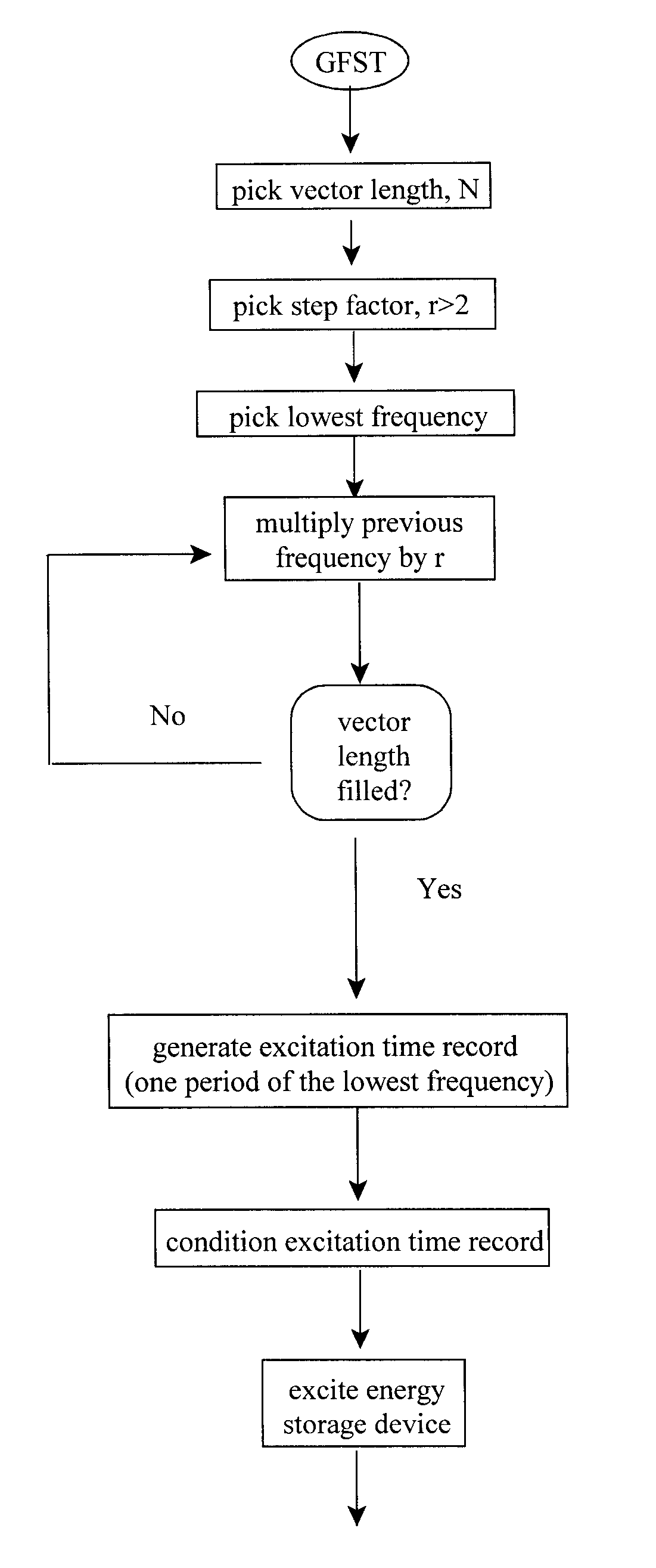
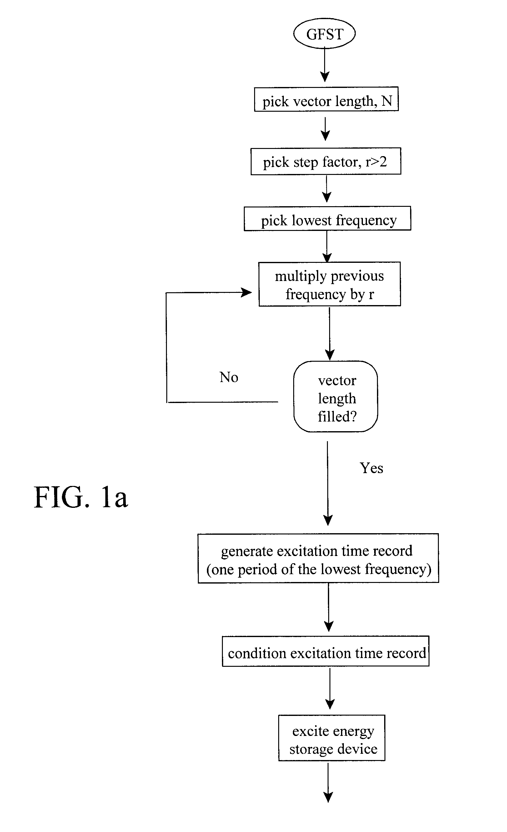
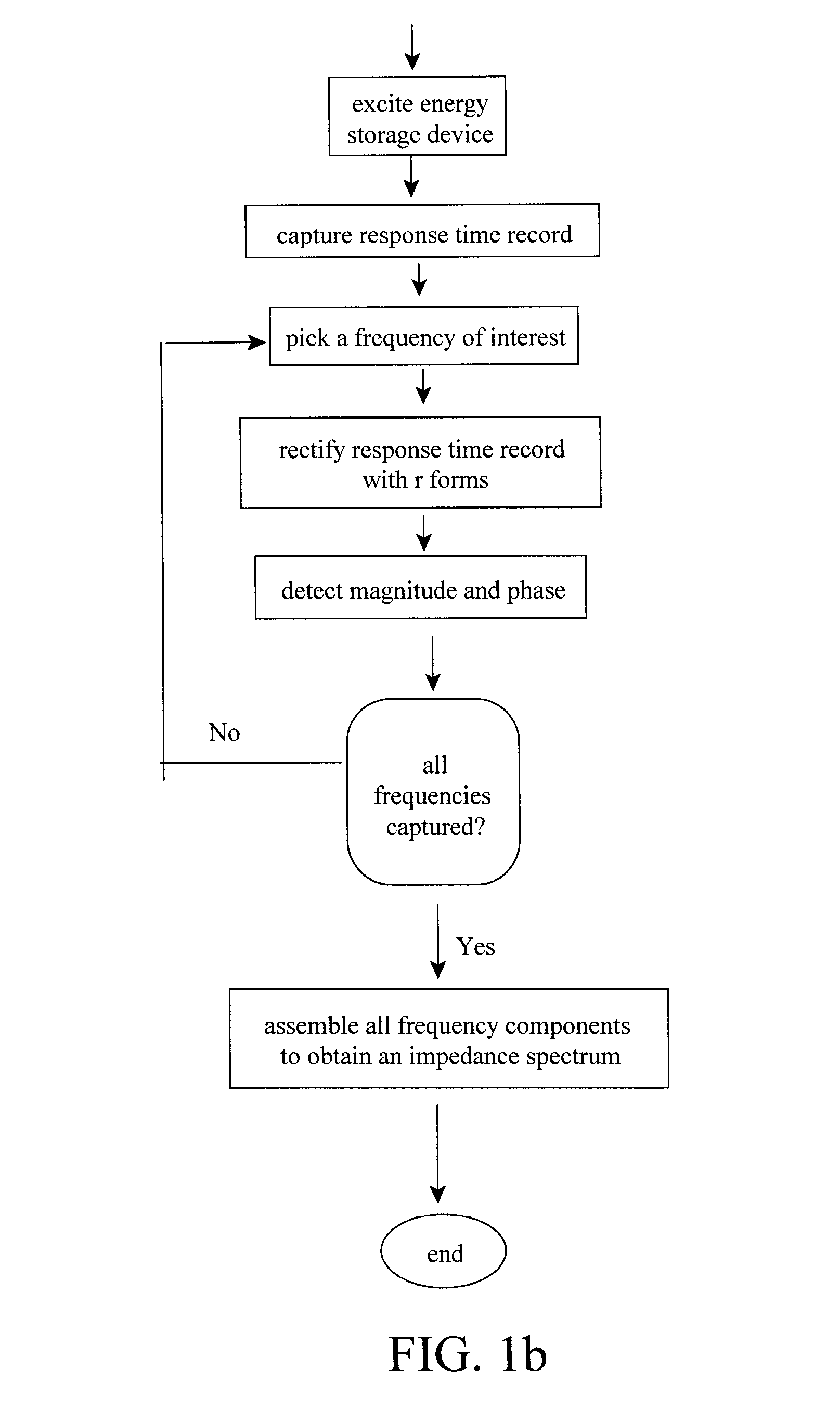
[0014]The method of the subject invention allows for rapid measurement of the impedance for energy storage devices. It has been shown that the shifts in the impedance spectra as a function of time and use strongly correlates to the health of, for example, battery technologies (Christophersen, 2002). Therefore, the subject method provides information about energy storage devices that is critical for onboard diagnostics and state-of-health estimation. The subject method measures the frequency response of an ESD (e.g., a battery) by exciting it with a SOS signal consisting of a number of select frequencies, and then capturing a response time record. The data are processed to obtain the impedance at each frequency in interest.

[0015]The desired frequencies are assembled as an excitation time record that can consist of a sum-of-sines signal with a length of, at most, one period of the lowest frequency. The response signal must be measured at a time step that is compatible with Shannon's s...


PUM


Abstract

Methods of rapidly measuring the impedance spectrum of an energy storage device in-situ over a limited number of logarithmically distributed frequencies are described. An energy storage device is excited with a known input signal, and the response is measured to ascertain the impedance spectrum. The excitation signal is a limited time duration sum-of-sines consisting of a select number of frequencies. In one embodiment, magnitude and phase of each of frequency of interest within the sum-of-sines is identified when the selected frequencies and sample rate are logarithmic integer steps greater than two. This technique requires a measurement with a duration of one period of the lowest frequency. In another embodiment, where the selected frequencies are distributed in octave steps, the impedance spectrum can be determined using a captured time record that is reduced to a half-period of the lowest frequency.

Description

CROSS-REFERENCE TO RELATED APPLICATIONS[0001]This application is a continuation-in-part of co-pending U.S. patent application Ser. No. 12 / 217,013, filed Jun. 30, 2008, which is a continuation-in-part of U.S. patent application Ser. No. 11 / 825,629, filed Jul. 5, 2007, now U.S. Pat. No. 7,395,163 B1, issued Jul. 1, 2008, which is a continuation of U.S. patent application Ser. No. 11 / 313,546, filed Dec. 20, 2005, now abandoned, which claims the benefits of U.S. Provisional Patent Application Nos. 60 / 637,969, filed Dec. 20, 2004 and 60 / 724,631, filed Oct. 7, 2005. This application further claims the benefits of U.S. Provisional Patent Application No. 61 / 186,358; filed Jun. 11, 2009. The disclosures of each of these applications are hereby incorporated by reference in their entirety, including all figures, tables and drawings.STATEMENT REGARDING FEDERALLY SPONSORED RESEARCH OR DEVELOPMENT[0002]This invention was made with Government support under Grant No. DE-AC07-05ID14517 awarded by th...

Claims


Application Information

Patent Timeline
IPC IPC(8): G01R23/00G06F19/00
CPCG01R31/2837
Inventor MORRISON, JOHN L.MORRISON, WILLIAM H.CHRISTOPHERSEN, JON P.
Owner BATTELLE ENERGY ALLIANCE LLC
Why Eureka
Try Eureka