
Digital processing method and system for determination of optical flow

Inactive Publication Date: 2010-05-20
CHEYTEC TECH LLC
View PDF7 Cites 32 Cited by
  • Summary
  • Abstract
  • Description
  • Claims
  • Application Information

AI Technical Summary

Benefits of technology

[0012]According to an embodiment of the present invention, the first pyramid scale may be the lowest resolution pyramid scale and another pyramid scale is next higher resolution pyramid scale. Step (c) may be accomplished using a spatiotemporal gradient estimation method. The optical flow estimation process may employ a least-squares-fit method.
[0013]According to an embodiment of the present invention, the method may further comprise the step of employing a pre-scaling step via bilinear interpolation to ensure that the highest resolution pyramid scale devolves to integer image sizes of width and height. The method may further comprising the step of processing the raw optical flow field with at least one non-linear filter that imposes a non-linear, piecewise-linearity constraint on the optical flow field. The at least one non-linear filter is at least one of non-linear low-pass, smoothing, and statistical regularization filter, which may be at least one of a total variation minimization (L1 and L2 norm) filter, an anisotropic diffusion filter, an elliptic steerable filter that reacts to local image structures, and a kernel regression filter.
[0014]According to an embodiment of the present invention, the method may further comprise the steps of employing performing multiple-pixel moti

Problems solved by technology

Known methods for calculating optical flow encounter several stumbling blocks.
Many methods suffer from low accuracy—motion vectors may not reflect the actual motion; others lack precision—motion vectors are limited to a precision on the order of a single pixel or a particular fraction of a pixel in a limited region; still others suffer from a lack of density—single motion vectors may be available only for entire regions or blocks of an image, instead of on a per-pixel basis.
Additionally, widely varying computational and memory bandwidth costs accrue to many, if not all, of these methods.
Block-based matching methods are frequently used in video coding and other real-time tasks due to their relatively small complexity and intuitive nature.
However, block-based matching methods are limited in dynamic range by the extent of a block search, limited in precision by the granularity of the block search, limited in the accuracy of an interpolator used to sample pixel values at the sub-pixel level, and limited in accuracy due to what is known as the “aperture problem.” The “aperture problem” occurs when a block matching method estimates a wrong motion vector due to lack of sufficient differences between blocks with no texture or edge differences along a gradient, which results in a motion vector at a local minimum instead of the global minimum.
Prior art block-based optical flow and motion-estimation methods suffer from the aperture problem, which is further exacerbated in block based methods that attempt to reduce search complexity by using multi-scale or other techniques to reduce the search depth and breadth from that of an exhaustive search.
As a result, motion-compensated block-based methods have found widespread application in the field of video coding, at the expense of reduced accuracy.
However, phase-based motion estimation is performed in the frequency domain and acts upon the phase information computed therein, and therefore requires input images to be transformed to the 2D frequency domain, a very computationally expensive process for video.
Unfortunately, these techniques still involve relatively applying large filter-banks sequentially to each pixel, resulting in a high memory bandwidth requirement with only a modest decrease in relative overall computational complexity and memory bandwidth requirements.
121-130 (hereinafter “Lucas and Kanade”), produce dense optical flow fields on a per-pixel basis, but cannot reliably generate motion vectors with magnitudes greater than a single pixel, and suffer from inconsistent flow fields in the presence of severe noise, object occlusions, and complex non-translational motion.
The method and system described in U.S. Pat. No. 5,680,487 overcomes the single-pixel limitation by using a multi-scale method, but is not robust in the presence of noise and / or occlusions.
A drawback to the approach used by Nagel and Enkelmann is that the gradient-constancy constraint is violated under complex motion models such as scaling and rotation.
Additionally, the estimation of discrete-space spatio-temporal derivatives under the scheme of Nagel and Enkelmann has proved to make error-free implementation problematic.
The foregoing prior art optical flow methods suffer from mathematical instability in the presence of noise and occlusions, and are further impaired by a consistently-applied, but very coarse approximation of the actual spatio-temporal gradient calculation upon which the rest of the estimation process is dependent (such as the central-differences method, which completely ignores the sampled values, at the actual sample location under analysis).
These coarse approximations lead to unnecessary errors in the initial estimation process, forcing subsequent stages to clean up or reject estimated values based upon further imperfect heuristics, thresholds, or constraints, all accomplished at a significant expense of further complexity.
The foregoing prior art optical flow methods further suffer from one or more of the problems of (1) high computational complexity, (2) noise susceptibility due to numerical instability, (3) failure to account for occlusions of pixels from one frame to the other, (4), limited range of motion, (5) inability to accurately calculate a flow field in the presence of changes of brightness due to lighting changes in the scene or of objects in the scene, and / or (6) accuracy problems due to incorrect or inadequate assumptions in the model of the discrete-sampled gradient field.

Method used


Image

  • Digital processing method and system for determination of optical flow
  • Digital processing method and system for determination of optical flow
  • Digital processing method and system for determination of optical flow

Examples


Embodiment Construction

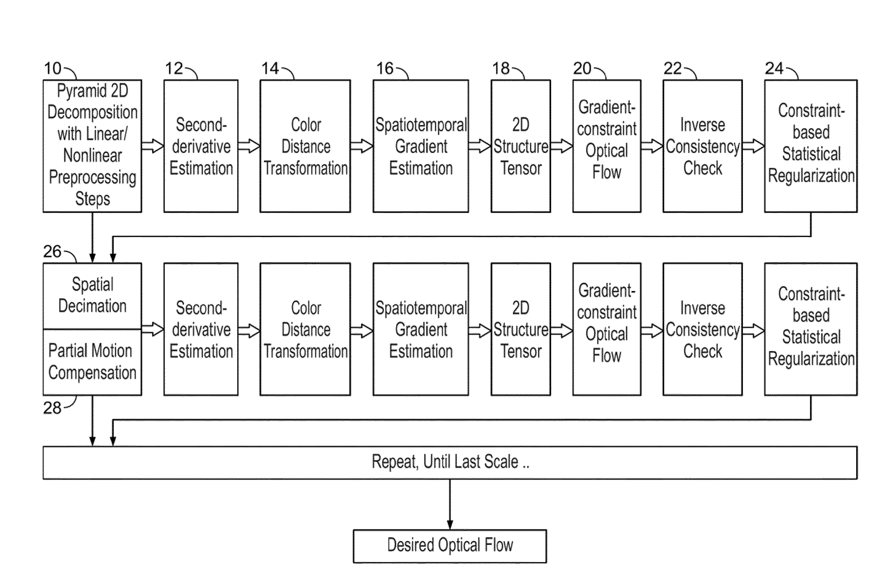
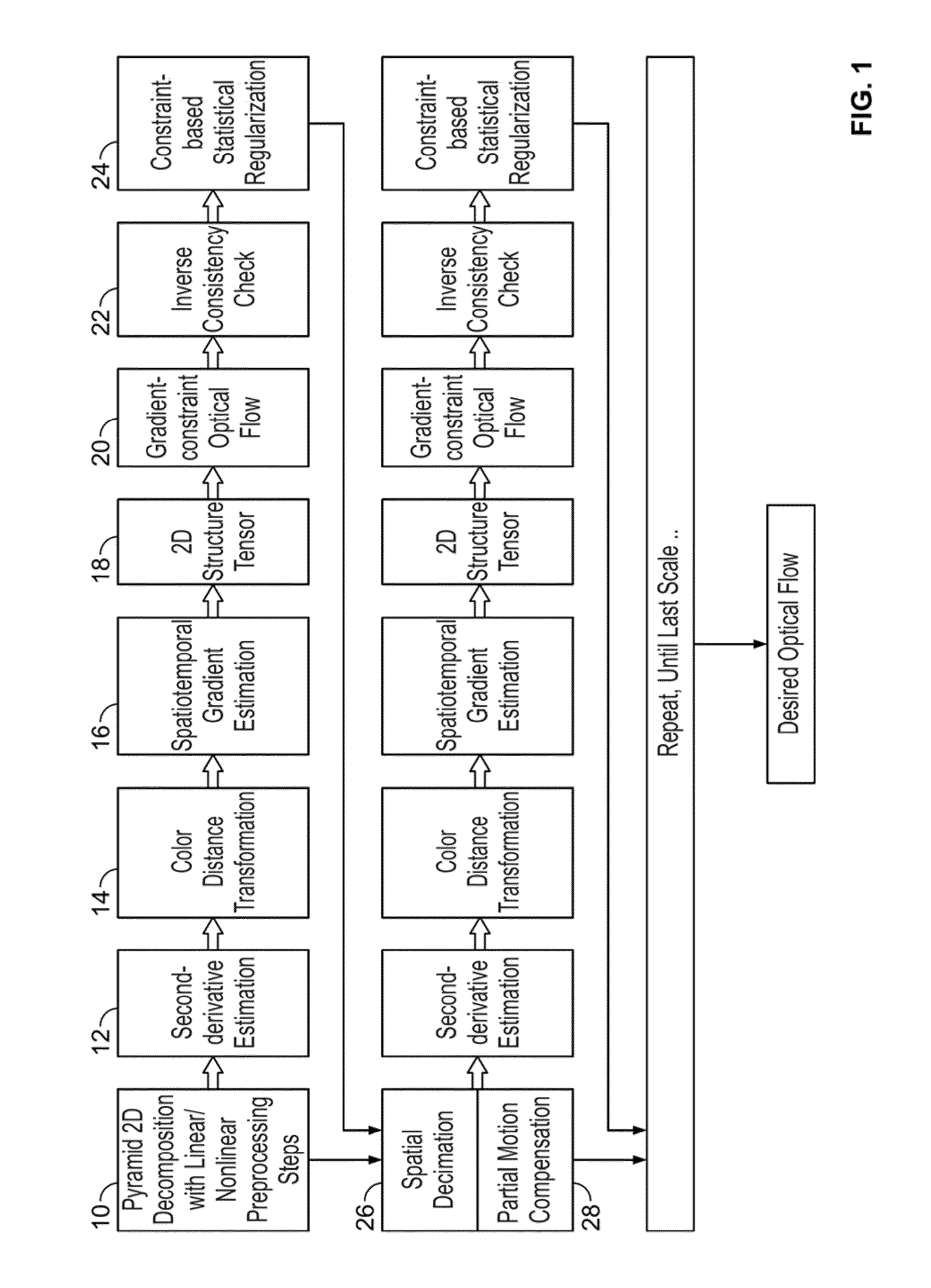
[0025]FIG. 1 depicts a process flow diagram illustrating exemplary steps for computing an optical flow field between a pair of images, according to an embodiment of the present invention. At step 10, each of the pair of images is decomposed into image pyramids. In the process of generating the image pyramids, at least one of several linear and / or non-linear filters may be applied to the decomposed pair of images. The image pyramids may be decomposed using arbitrary scaling factors less than one-octave-per-level in order to reduce the problem of later estimation steps being fixated at a local minimum instead of the global minimum, thereby preventing what is known as an “aperture problem.” At step 12, at the lowest resolution image pyramid scale, the pair of decomposed images is transformed to second derivative representations under an assumption that the brightness gradient (or, alternatively, the second derivative of the brightness) is assumed to be constant. At step 14, the second ...


PUM


Abstract

A method and system for determining an optical flow field between a pair of images is disclosed. Each of the pair of images is decomposed into image pyramids using a non-octave pyramid factor. The pair of decomposed images is transformed at a first pyramid scale to second derivative representations under an assumption that a brightness gradient of pixels in the pair of decomposed images is constant. Discrete-time derivatives of the second derivative image representations are estimated. An optical flow estimation process is applied to the discrete-time derivatives to produce a raw optical flow field. The raw optical flow field is scaled by the non-octave pyramid factor. The above-cited steps are repeated for the pair of images at another pyramid scale until all pyramid scales have been visited to produce a final optical flow field, wherein spatiotemporal gradient estimations are warped by a previous raw optical flow estimation.

Description

CROSS-REFERENCE TO RELATED APPLICATIONS[0001]This application claims the benefit of U.S. provisional patent application No. 61 / 105,515 filed Oct. 15, 2008, the disclosure of which is incorporated herein by reference in its entirety.FIELD OF THE INVENTION[0002]The present invention relates generally to digital image processing, and mom particularly, to a method and system for automatic determination of an optical flow field between a pair of images.BACKGROUND OF THE INVENTION[0003]Determining an optical flow field between two images, particularly for sequences of video frames and / or fields, is frequently encountered step in many high-value video processing tasks such as coding, frame rate conversion, noise reduction, etc. Known methods for calculating optical flow encounter several stumbling blocks. Many methods suffer from low accuracy—motion vectors may not reflect the actual motion; others lack precision—motion vectors are limited to a precision on the order of a single pixel or a...

Claims


Application Information

Patent Timeline
IPC IPC(8): G06K9/00
CPCG06T7/2066G06T7/2073G06T7/20G06T2207/20016G06T2207/10016G06T7/207G06T7/269H04N7/12
Inventor GADDY, WILLIAM L.
Owner CHEYTEC TECH LLC
Learn More