
Tunable vibration absorbing device

a vibration absorption and absorbing device technology, applied in the direction of shock absorbers, springs/dampers, ways, etc., can solve the problems of increasing concerns about environmental railway noise and methods that are not universally accepted, and achieve the effects of reducing overall energy absorption, reducing noise, and reducing vibration

Active Publication Date: 2013-01-15
HO WAI LUN
View PDF8 Cites 3 Cited by
  • Summary
  • Abstract
  • Description
  • Claims
  • Application Information

AI Technical Summary

Benefits of technology

The present invention is a device that reduces noise and vibration in railways. It contains an oscillation mass and a mounting member separated by a resilient layer. The invention solves the problem of small movement gaps between the damper and the rail, which traditional methods of fixing the damper by clamping or gluing introduce. The device can be quickly fitted and easily installed during non-operating hours of the railroad, which makes it efficient in reducing energy loss and improving energy absorption.

Problems solved by technology

Environmental railway noise has drawn increasing concerns as railway lines extended into residential areas.
However, installation of dampers on operating urban rails is normally restricted to 2 to 4 non-service hours in midnight, thus such methods are not universally accepted.

Method used


Image

  • Tunable vibration absorbing device
  • Tunable vibration absorbing device
  • Tunable vibration absorbing device

Examples


Embodiment Construction

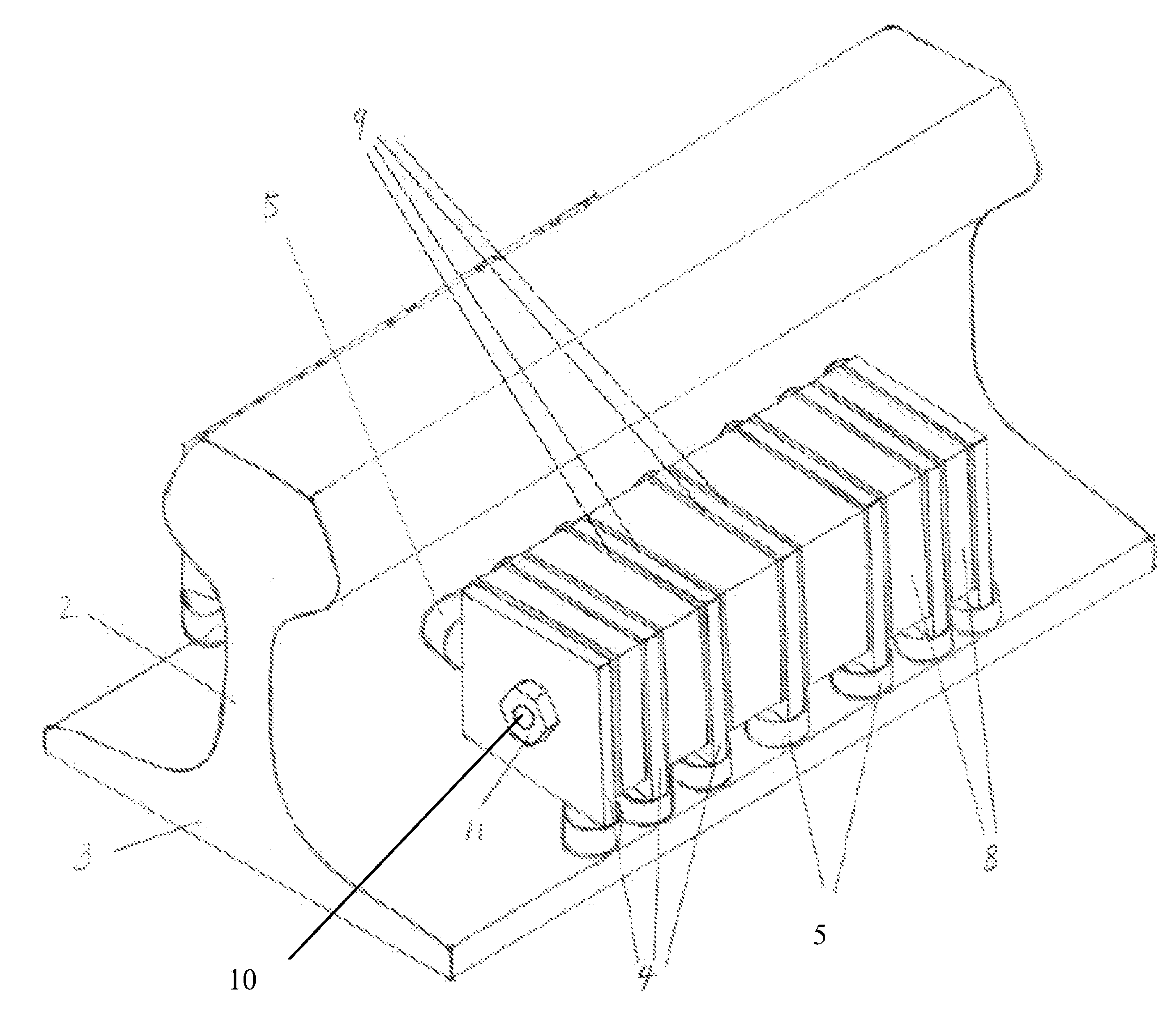
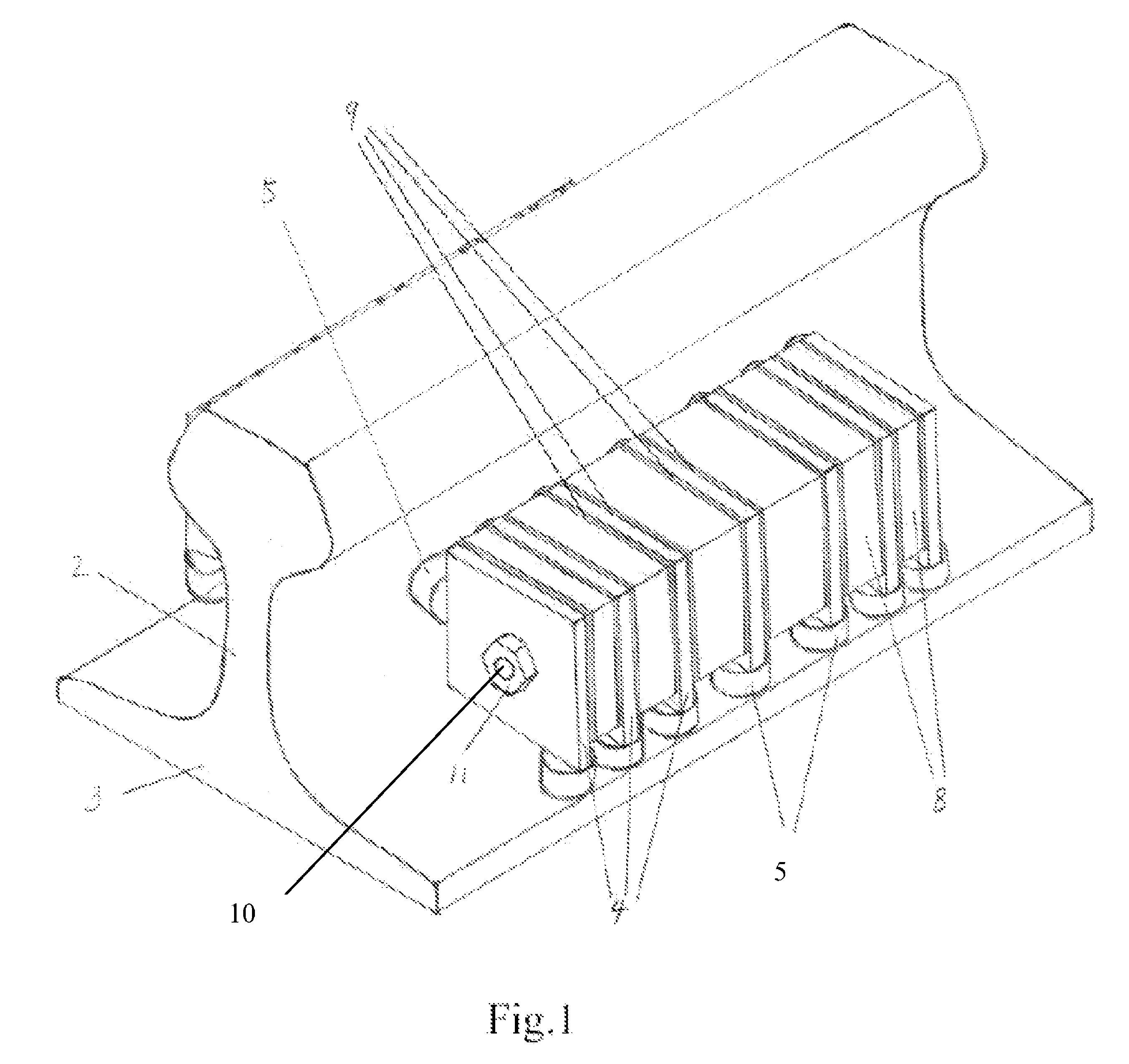
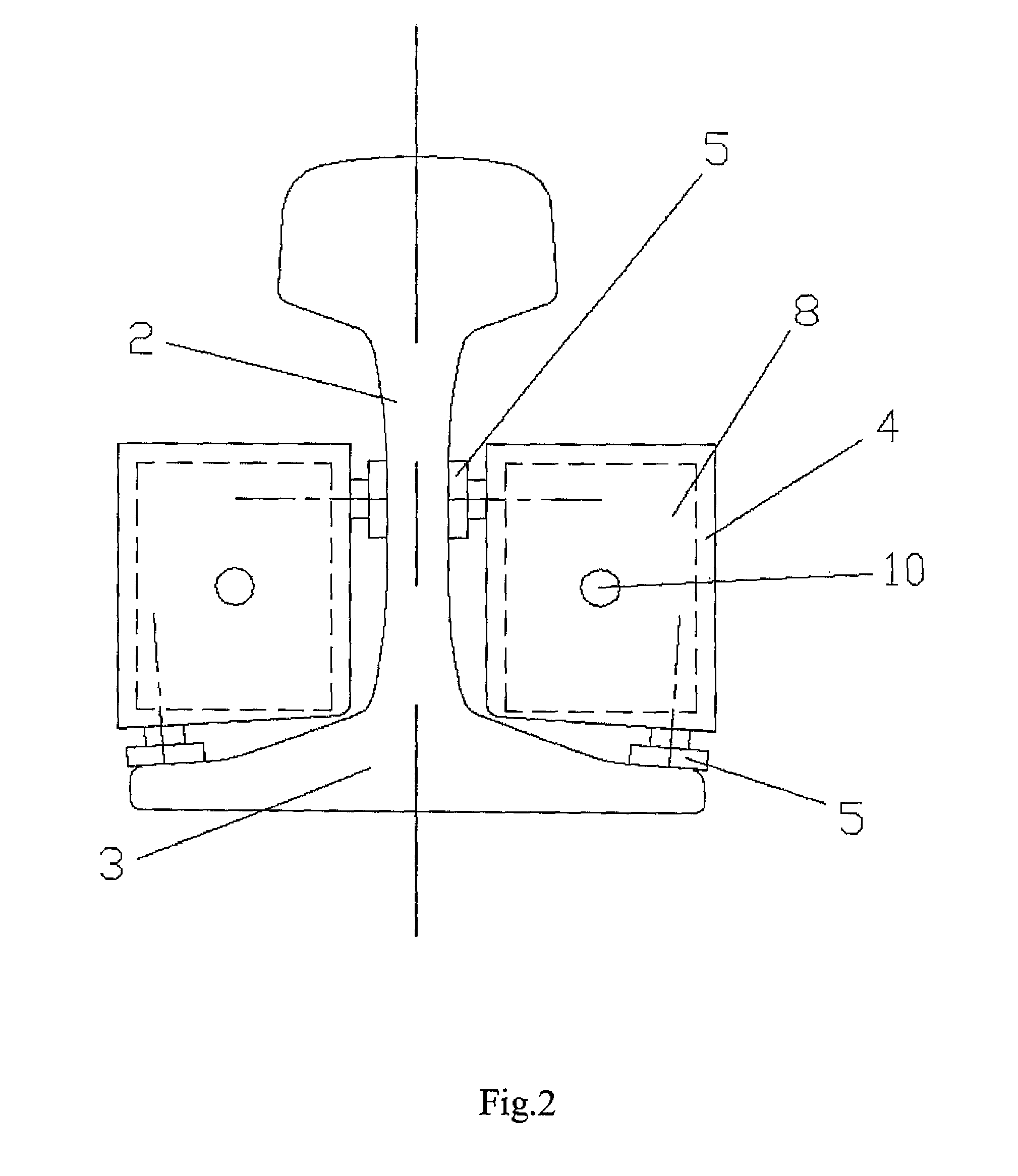
[0015]Referring now to FIG. 1, in a first embodiment of the present invention, the damper includes a series of oscillation masses 8 of different sizes attached to the rail via several steel mounting members, or mounting plates 4. The oscillation masses are made of steel or other high-density materials. They are held in position by layers of resilient material 9 such as natural rubber or synthetic rubbers like silicone rubbers, neoprene, polyurethane, etc. Each mounting plate 4 is fixed to the rail by a magnetic object which includes two magnets 5. A bolt 10 is inserted through the mounting plates 4, resilient layers 9 and oscillation masses 8 alternatively. The bolt 10 is fixed to one of the middle mounting plates 4 such that different compressive forces can be provided on the two sides by tightening the nuts 11 installed on two ends of the said bolt to different pre-set torques. The bolt and nuts compose a fastener.

[0016]FIG. 2 shows an exemplary embodiment of the invention, where ...


PUM


Abstract

A Tuned Mass Damper (TMD) for reducing vibration and noise radiation from rails incorporates a series of oscillation mass (8) of different sizes held in position by layers of resilient material (9) and attached to the rail via several steel mounting plates (4). Each mounting plate (4) is fixed to the rail by two magnets (5). A bolt (10) is inserted through the mounting plates (4), resilient layers (9) and oscillation masses (8) alternatively. The bolt (10) is fixed to a middle mounting plate (4) such that different compressive forces can be provided on the two sides by tightening nuts (11) to different pre-set torques. When the resonance frequency of the oscillation masses (8) is tuned to that of rail, most of the rail vibration energy at resonance frequency is transferred to the oscillation masses (8) and eventually dissipated in the resilient layers (9).

Description

CROSS-REFERENCE TO RELATED APPLICATION[0001]This application claims benefit under 35 U.S.C. §119(e) of U.S. Provisional Application having Ser. No. 60 / 985,986 filed Nov. 7, 2007, which is hereby incorporated by reference herein in its entirety.RELATED APPLICATIONS[0002]This patent application is a National Stage of International Application Serial No. PCT / CN2008 / 072369, filed Sep. 16, 2008, which claims the benefit of U.S. provisional application Ser. No. 60 / 985,986, filed on Nov. 7, 2007, the disclosures of which are all incorporated herein by reference in their entireties.FIELD OF INVENTION[0003]This invention relates to a device for vibration absorption, and in particular a vibration absorbing device for reducing vibration and noise radiation from rails.BACKGROUND OF INVENTION[0004]Environmental railway noise has drawn increasing concerns as railway lines extended into residential areas. Wayside noise barriers are commonly used to reduce the noise impacts on nearby residents. In ...

Claims


Application Information

Patent Timeline
Patent Type & Authority Patents(United States)
IPC IPC(8): E01B19/00F16F7/10
CPCE01B19/003
Inventor HO, WAI LUN
Owner HO WAI LUN
Learn More