
System and methods for controlling movement of a track light system

a track lighting and movement technology, applied in the field of electronic devices, can solve the problems of uneven growth process, waste of light and power relative to the potential amount of energy of plants, etc., and achieve the effect of no significant drain of resources and no significant increase in plant growth speed and health results

Inactive Publication Date: 2013-01-22
CARTWRIGHT BRENT A
View PDF5 Cites 29 Cited by
  • Summary
  • Abstract
  • Description
  • Claims
  • Application Information

AI Technical Summary

Benefits of technology

[0012]The present inventor realized in an inventive moment that if, at the point of activation, a track lighting system could be caused to move and stop for preset periods of time over the plants, significant growth might result. The inventor therefore constructed a unique control system for a track light system that allowed photosynthesis to occur in the plants at a more robust level, but constrained constant back and forth movement of the track light system over the plants. A significant uptake in plant growth speed and health results, with no significant drain on resources including energy.

Problems solved by technology

The problem stated above is that adequate lighting is desirable for an indoor garden area, but many of the conventional means for lighting the indoor garden area, such track light system, also create an uneven growing process and a waste of light and power relative to the potential amount of energy the plants can produce.

Method used


Image

  • System and methods for controlling movement of a track light system
  • System and methods for controlling movement of a track light system
  • System and methods for controlling movement of a track light system

Examples


Embodiment Construction

[0027]The inventor provides a unique control system for a motorized track light system enabling photosynthesis to occur in the plants at a more robust level. The new system incorporates preset timeouts into the movement of the system. The present invention is described in enabling detail in the following examples, which may represent more than one embodiment of the present invention.

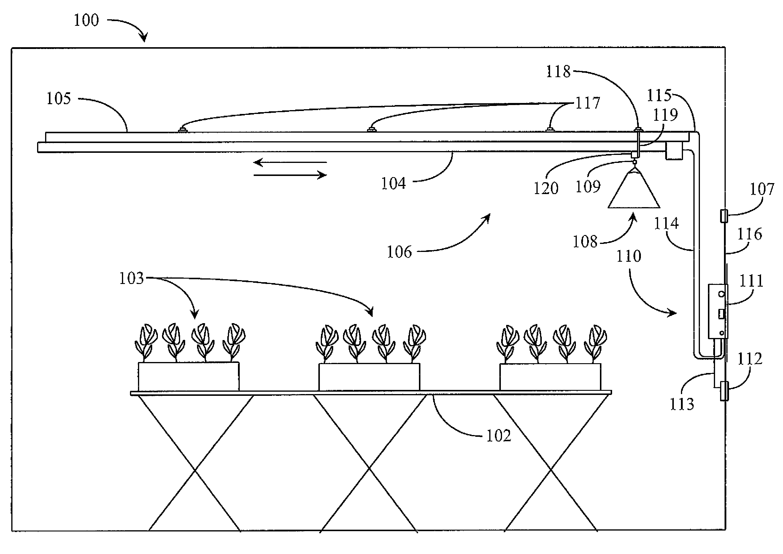
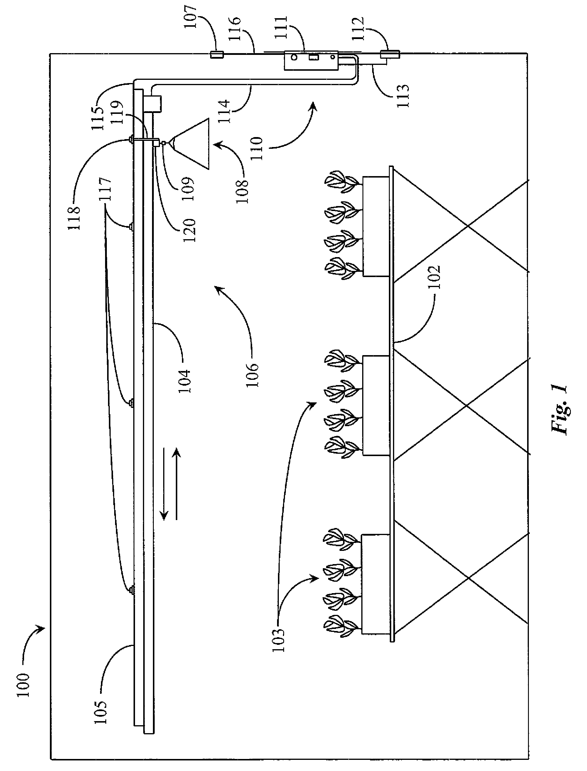
[0028]FIG. 1 is an elevation view of an indoor garden 100 with a track lighting system according to an embodiment of the present invention. Garden 100 is in this example an indoor garden that produces commercially for the consumer market. Indoor garden 100 has a plurality of plants 103 arranged in planter boxes and spaced evenly apart in rows on a table or other platform apparatus 102. In this view only the ends boxes with plants 103 are visible in each of four illustrated rows.

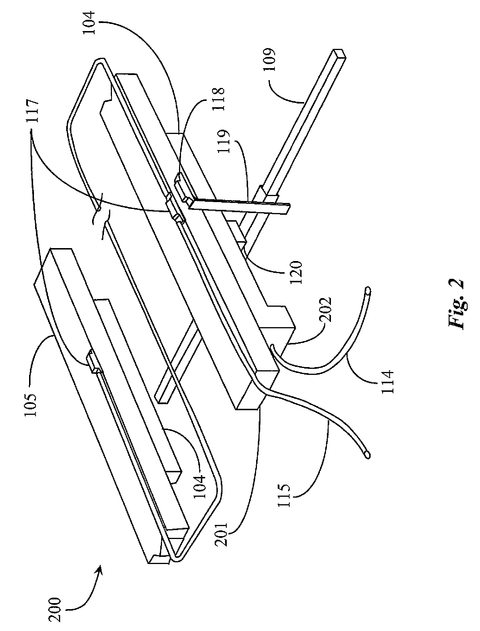
[0029]Indoor garden 100 has a motor driven track lighting system 106 supported by a track 104 and a support beam 105. In this ex...


PUM


Abstract

A system for controlling a motorized track light system constrained to travel along a track has a control unit coupled to a motor that causes the track light system to move along the track, a plurality of stop sensors strategically disposed along the track, a sensor activation device located on the track light system, the sensor activation device positioned to interface with the stop sensors, and a light sensor for detecting ambient light of a preset level. The system detects a preset level of ambient light, initiating power to the motor of the track light system, moving the lights along the track until the activation device interfaces with a first of the plurality of stop sensors, stopping movement of the track light system along the track for a preset period of time, and at the end of the preset time period, the electrical power is restored to the motor moving the track light assembly along the track to the next of the plurality of stop sensors.

Description

CROSS-REFERENCE TO RELATED APPLICATIONS[0001]The present application claims priority to U.S. provisional patent application Ser. No. 61 / 097,371, filed on Sep. 16, 2008. The entire disclosure is included herein in its entirety at least by reference.BACKGROUND OF THE INVENTION[0002]1. Field of the Invention[0003]The present invention is in the field of electronics and pertains particularly to methods and apparatus for controlling a track lighting system.[0004]2. Discussion of the State of the Art[0005]In the field of agriculture, indoor gardens with artificial lighting are leveraged to incubate and grow a wide variety of plants for the consumer market. Plants in an indoor garden are subject to temperature control and controlled artificial lighting adapted to mimic natural sunlight.[0006]Some proprietors of indoor gardens employ motorized track lighting systems, termed light movers, to incubate and grow plants as opposed to fixed lighting systems. One advantage of a moving lighting sys...

Claims


Application Information

Patent Timeline
Patent Type & Authority Patents(United States)
IPC IPC(8): G05B1/06
CPCA01G9/26F21V21/15F21V21/35F21V23/0442A01G7/045A01G9/249Y02A40/25
Inventor CARTWRIGHT, BRENT A.
Owner CARTWRIGHT BRENT A
Learn More