Trim actuator actuating system for a hydraulically actuatable trimmable horizontal stabilizer actuator

a technology of trimmable horizontal stabilizer and trimmable actuator, which is applied in the direction of actuating personally, couplings, fluid couplings, etc., can solve the problems of high requirement placed on trim actuators, which is 110sup>6 /sup>l/h, and may not be achieved using a piston cylinder unit of this type alone, so as to achieve secure maintenance of forces in magnitude and repair easy

Inactive Publication Date: 2013-01-29
AIRBUS OPERATIONS GMBH
View PDF17 Cites 9 Cited by
  • Summary
  • Abstract
  • Description
  • Claims
  • Application Information

AI Technical Summary

Benefits of technology

[0010]Since the specified known breakdown probability of a linear actuator of approximately 1·10−4 l / h relates to a linear actuator having only one hydraulic power supply system, by providing an autonomous second hydraulic power supply system, the breakdown probability may be reduced to the required target value of 1·10−6 l / h or less. In addition, the trim actuator actuating system according to the present invention may have a less complex construction than known spindle actuators, through which the weight of the trim actuator may be significantly reduced. In addition, a hydraulic linear actuator may have a significantly smaller overall volume than the known threaded spindles to be provided redundantly, which is desirable at all times in the field of aerospace engineering, of course. A further advantage achievable with the aid of the trim actuator actuating system according to an embodiment of the present invention may be that higher adjustment speeds may be implemented using a hydraulic linear actuator as is usable in the trim actuator actuating system according to an exemplary embodiment of the present invention than using typical trim actuators employing threaded spindles.
[0014]So that completely separate lines do not have to be laid for the power supply to the at least one linear actuator using the second power supply system, the second power supply system may be coupled to the first power supply system to apply hydraulic power to the first power supply system in this way during malfunction operation. In this way, additional weight may be saved, which is a principle always to be maintained in the field of aerospace engineering.
[0019]By the development of the mechanical lock suggested here and by the redundant power supply system, a completely new area of application may be opened up for linear actuators (electrical, hydraulic, or pneumatic), through which the use of piston cylinder units as trimmable horizontal stabilizer actuators may be made possible. By the mechanical lock, the linear actuator may be capable of securely maintaining its last set position if the power supply breaks down, for which it may not require any further power, as will be explained in greater detail in the following. In contrast to known frictional locks of piston cylinder units, a linear actuator equipped with the lock according to an exemplary embodiment of the present invention may be, with corresponding dimensioning of the lock, capable of securely maintaining forces in the magnitude of the positioning forces applied by the linear actuator itself.
[0020]Since the lock is essentially situated in the area of the outer circumference of the linear actuator or its cylinder, the lock may be inspected, maintained, tested, and even repaired easily at any time if necessary. Since the lock may transmit the forces from the cylinder to the piston rod if the two power supply systems to the linear actuator break down, it may represent a second load path, via which the loads of the linear actuator may be dissipated safely in case of power breakdown.

Problems solved by technology

Since known piston cylinder units have breakdown probabilities of approximately 1·10−4 l / h, the high requirement placed on trim actuators, which is 1·10−6 l / h, may not be achieved using a piston cylinder unit of this type alone.
Since this required breakdown probability may not be achieved using a typical piston cylinder unit, until now those skilled in the art saw themselves as being prevented from using typical piston cylinder units of this type as trim actuators.

Method used


Image

  • Trim actuator actuating system for a hydraulically actuatable trimmable horizontal stabilizer actuator
  • Trim actuator actuating system for a hydraulically actuatable trimmable horizontal stabilizer actuator
  • Trim actuator actuating system for a hydraulically actuatable trimmable horizontal stabilizer actuator

Examples


Embodiment Construction

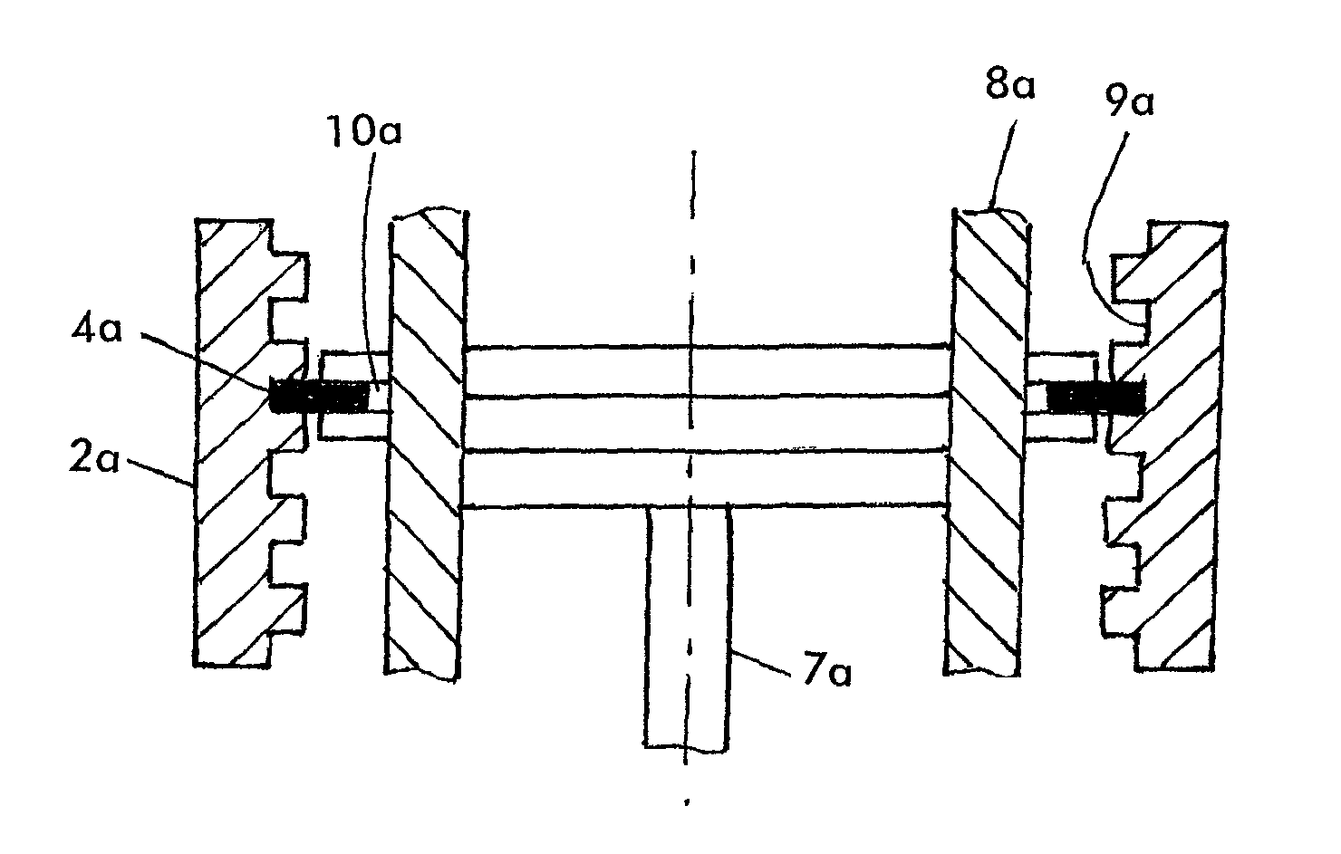
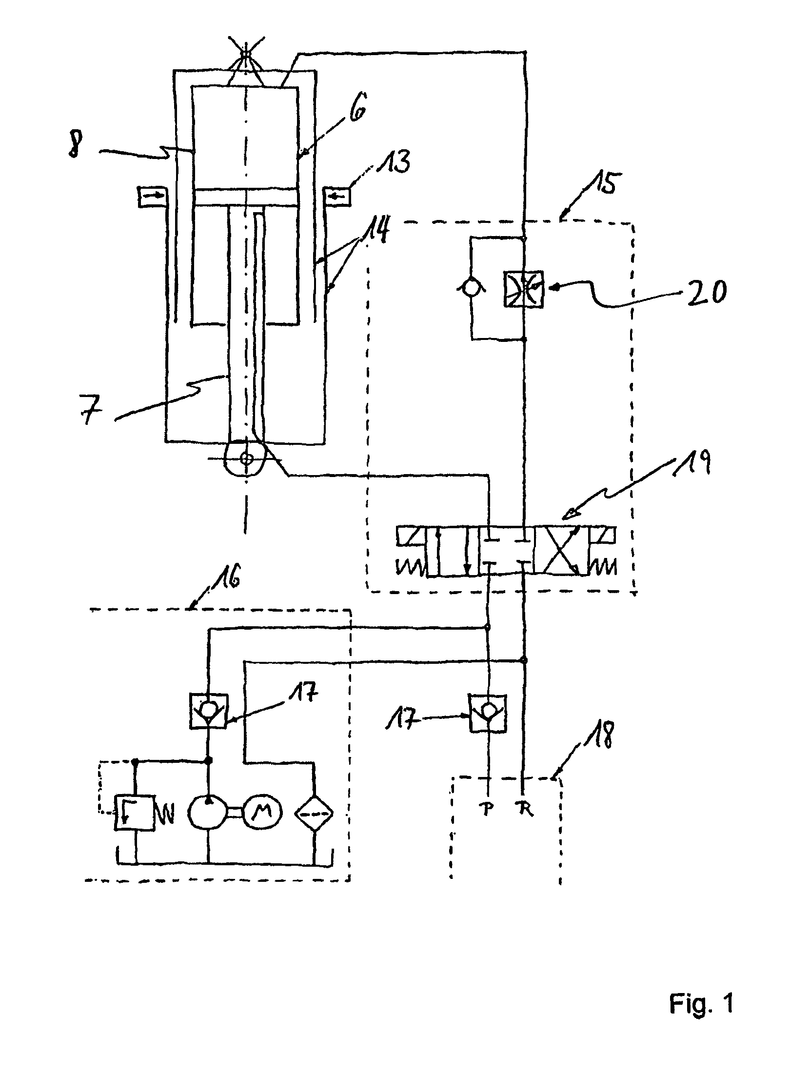
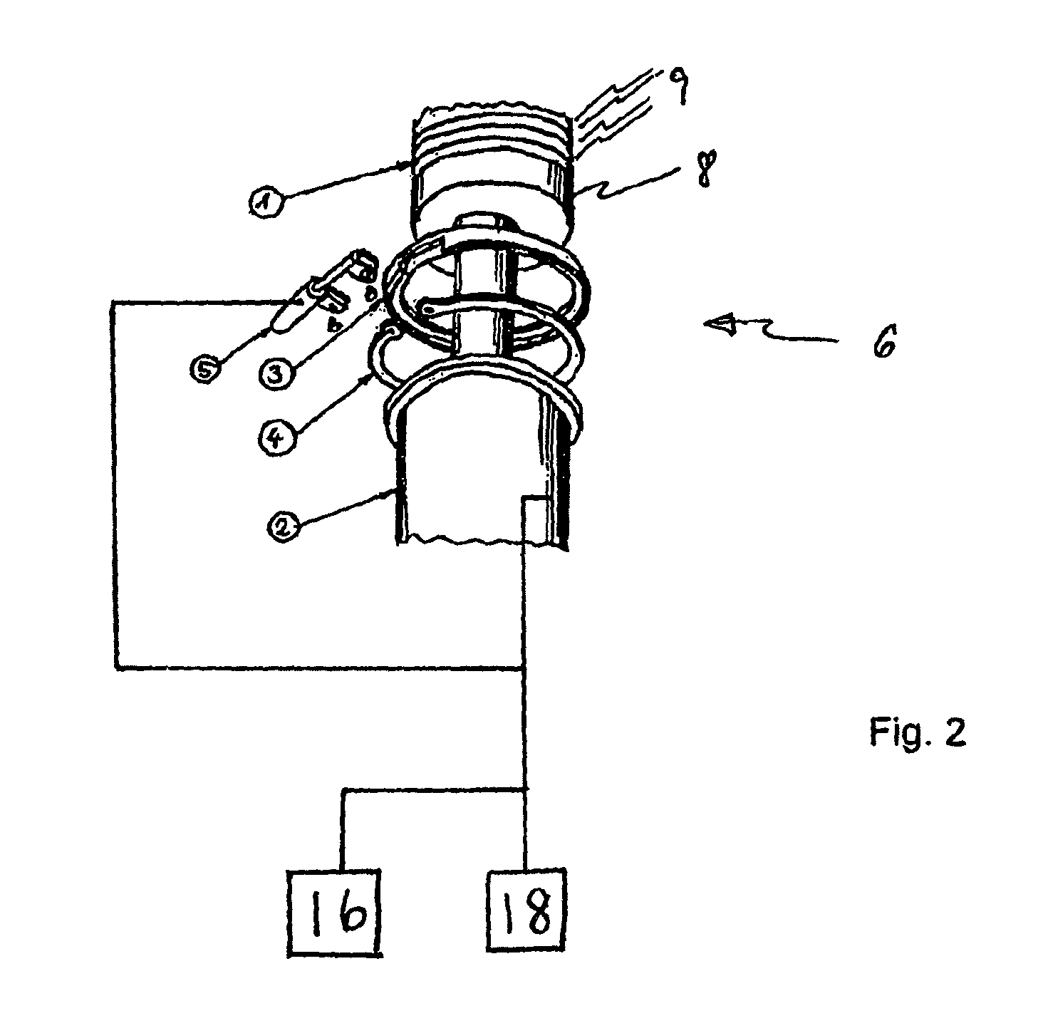
[0038]In the following, the trim actuator actuating system according to an exemplary embodiment of the present invention is explained first with reference to the hydraulic circuit diagram of FIG. 1. The trim actuator actuating system shown in FIG. 1 comprises a hydraulic linear actuator 6, a first power supply system 18, and a second power supply system 16, the second power supply system 16 being operated via a separate electrical hydraulic fluid pump. The linear actuator 6 has an external lock 13, which will be explained in greater detail in the further course of this description of the figures, and which is used as a second security stage in case of breakdown of the two power supply systems 16, 18. At this stage it is only noted that an external second load path is opened by the lock 13, via which the loads of the hydraulic cylinder may be transferred in the event of a power breakdown.

[0039]The linear actuator 6 has hydraulic power applied to it in the form of hydraulic pressure v...


PUM


Abstract

The present invention relates to a trim actuator actuating system having two separate hydraulic power supply systems, through which it is possible for the first time to use a hydraulic linear actuator as a trimmable horizontal stabilizer actuator in an aircraft. The at least one hydraulic linear actuator is coupled to the first power supply system in such a way that it applies hydraulic power to the linear actuator during normal operation. In order to ensure the application of pressure to the hydraulic linear actuator in case of breakdown, in such a case, the pressure application to the hydraulic linear actuator is maintained with the aid of the second hydraulic power supply system.

Description

CROSS REFERENCE TO RELATED APPLICATIONS[0001]The present application is a 35 U.S.C. §§371 national phase conversion of International application No. PCT / EP2006 / 008696, filed Sep. 6, 2006, which claims priority of German Patent Application No. 10 2005 042 511.9, filed Sep. 7, 2005, and U.S. Provisional Application No. 60 / 714,918, filed Sep. 7, 2005, the disclosures of which have been incorporated herein by reference. The PCT International Application was published in the English language.TECHNICAL FIELD[0002]The present invention relates in general to supplying hydraulic consumers in aircraft with power. In particular, the present invention relates to a trim actuator actuating system for a hydraulically actuatable trimmable horizontal stabilizer actuator in an aircraft. Furthermore, the present invention relates to the use of such a trim actuator actuating system in an aircraft to actuate at least one trimmable horizontal stabilizer actuator. In the relevant technical terminology, li...

Claims


Application Information

Patent Timeline
Patent Type & Authority Patents(United States)
IPC IPC(8): F15B15/26
CPCB64C13/42F15B15/149F15B15/261F15B20/004F15B2211/20576F15B2211/2654F15B2211/30525F15B2211/40584F15B2211/7053F15B2211/8633F15B2211/8757Y02T50/44Y02T50/40
Inventor HAASE, GUNNAR
Owner AIRBUS OPERATIONS GMBH
Why Eureka
Try Eureka