

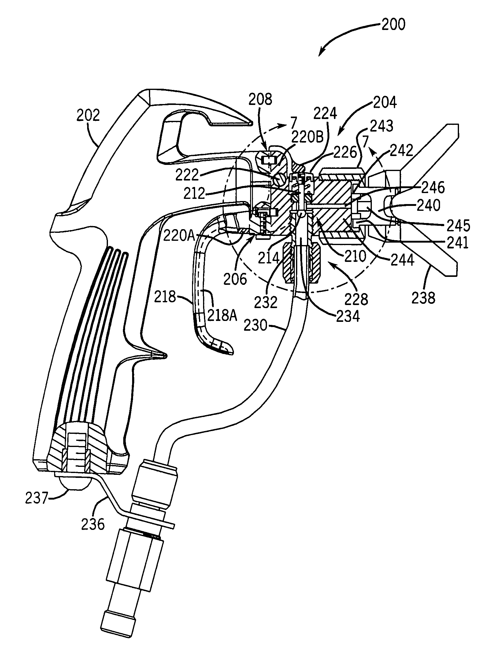
Airless spray gun having overhead valve and removable head
a spray gun and airless technology, applied in the direction of valve housing, valve operating means/releasing devices, mechanical equipment, etc., can solve the problems of inconvenient device use, burdening the user during and complicating the operation of the spray coating devi
- Summary
- Abstract
- Description
- Claims
- Application Information
AI Technical Summary
Benefits of technology
Problems solved by technology
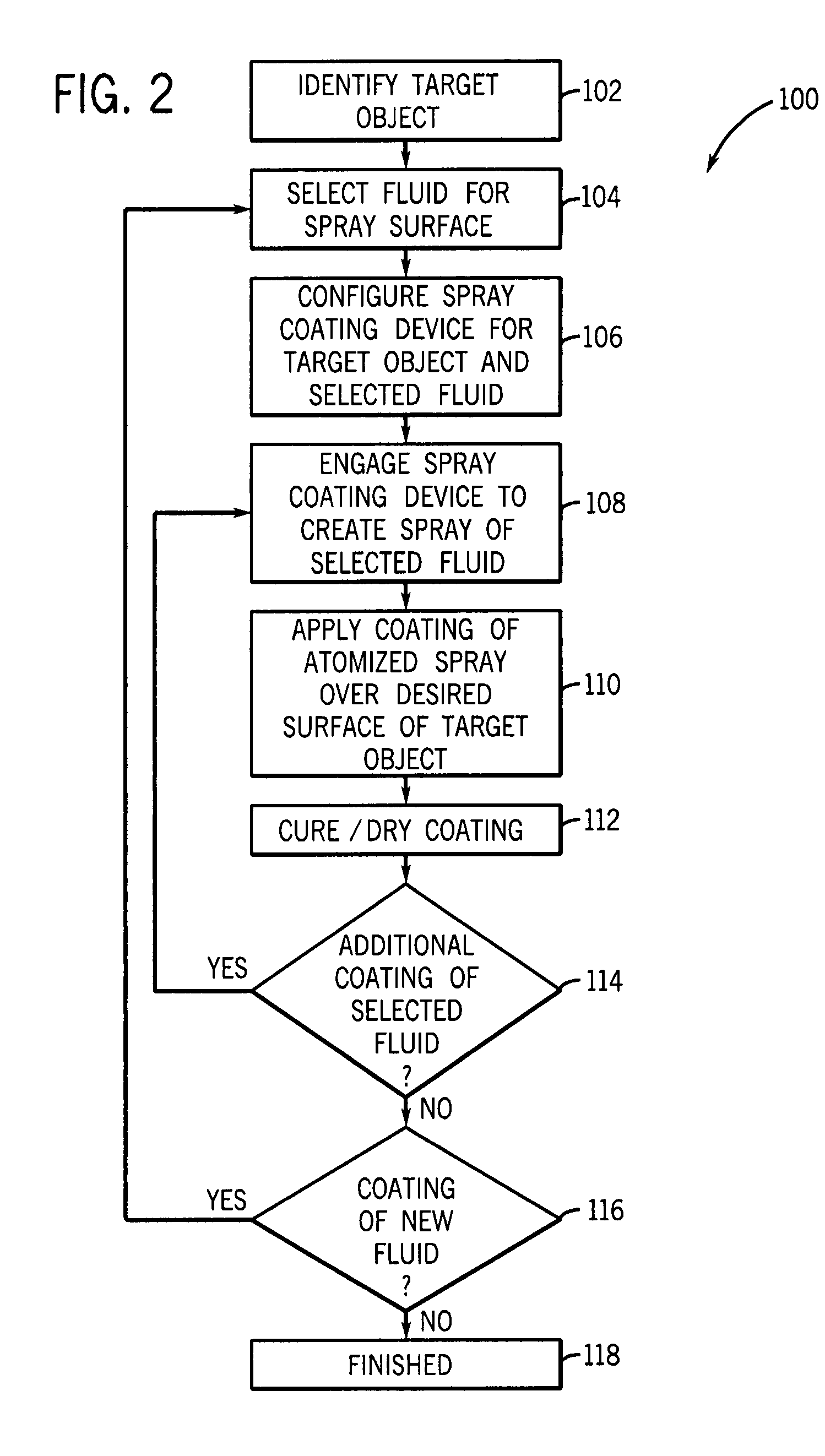
Method used
Image

Examples
Embodiment Construction
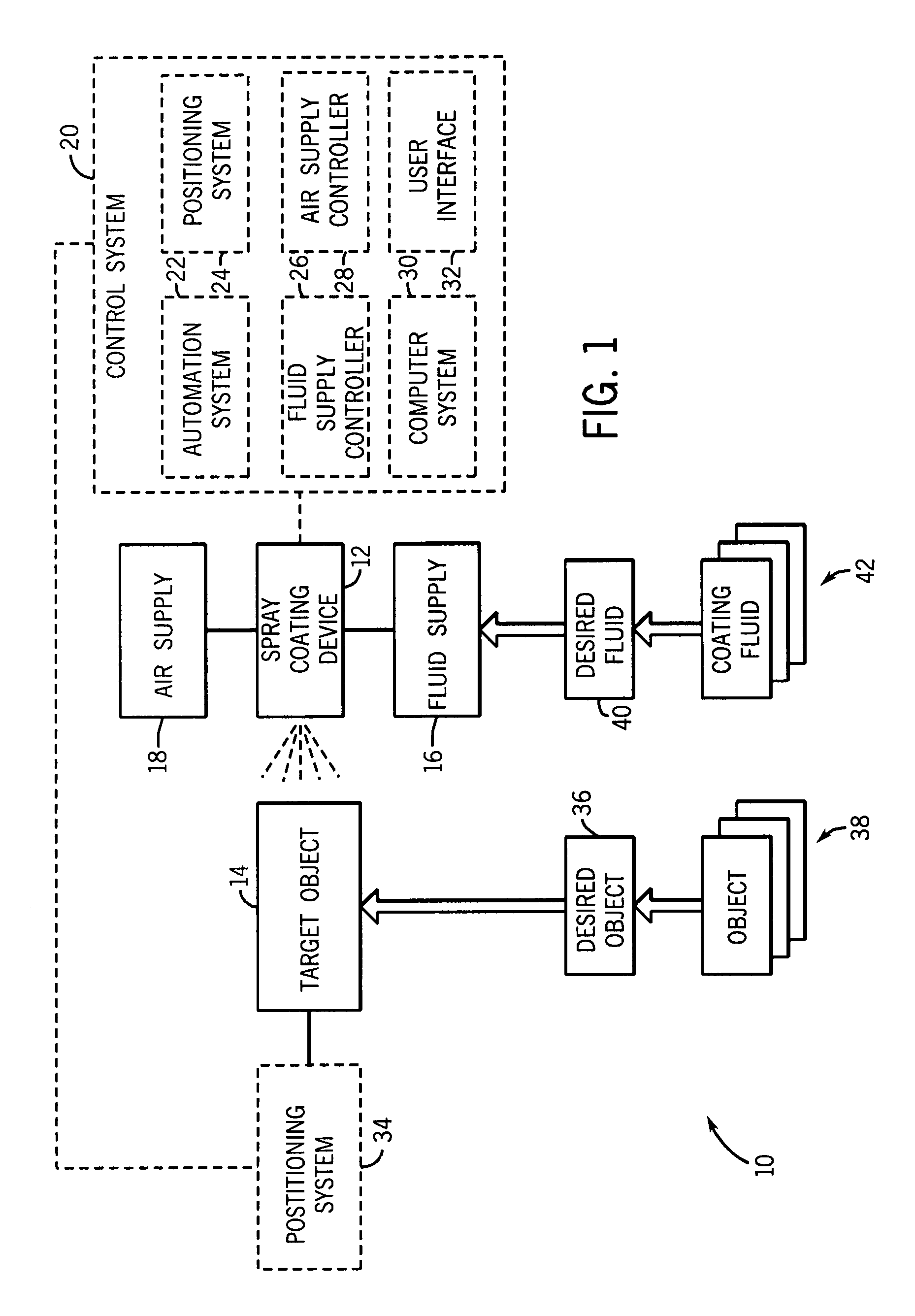
[0014]FIG. 1 is a flow chart illustrating an exemplary airless spray coating system 10, which comprises an airless spray coating device 12 for applying a desired coating to a target object 14. For simplicity, the airless spray coating device 12 will be described as an airless gun in the following description, although various embodiments of the airless spray coating device 12 may or may not have a gun-shaped body. In certain embodiments, the airless gun 12 has a detachable / removable fluid head, which further includes an overhead fluid valve assembly with an integral trigger. The airless gun 12 may be coupled to a variety of supply and control systems, such as a fluid supply 16 and a control system 20. The control system 20 ensures that the airless gun 12 provides an acceptable quality spray coating on the target object 14. For example, the control system 20 may include an automation system 22, a positioning system 24, a fluid supply controller 26, a computer system 30, and a user in...
PUM
 Abstract
Description
Claims
Application Information