System and method for determining placement of photovoltaic strips using displacement sensors

a technology of displacement sensor and photovoltaic strip, which is applied in the direction of pv power plants, controlling lamination, other domestic articles, etc., can solve the problems of reducing the efficiency of photovoltaic strips. , to achieve the effect of maximizing the capture of solar ligh

Inactive Publication Date: 2013-01-29
SOLARIA CORP
View PDF2 Cites 0 Cited by
  • Summary
  • Abstract
  • Description
  • Claims
  • Application Information

AI Technical Summary

Benefits of technology

[0010]In various embodiments, the characterization data (e.g. actual exitant illumination location) may be used as input for a PV strip placement operation with respect to the sheet of material. For example, such characterization data may be used by a user to determine where to place a PV strip relative to the sheet of material. As another example, such characterization data may be used by a machine or device that can pick PV strips and accurately position the PV strip relative to the sheet of material. In various embodiments, the placement of the PV strip relative to the sheet of material is intended to maximize the capture of solar light by the PV strip.
[0011]In various embodiments of the present invention, based upon physical geometry of test light concentrators and the characterization data (e.g. actual exitant illumination location) a mathematical model of the material may be determined. Subsequently, based upon the physical geometry of an unknown concentrator, based upon the mathematical model of the material, predicted characterization data (e.g. predicted exitant illumination locations) can be determined. In various embodiments, PV strips can be placed at the predicted exitant illumination manually, semiautomatically, or automatically with a machine or device mentioned above. In various embodiments, the placement of the PV strip relative to the sheet of material is intended to maximize the capture of solar light by the PV strip.

Problems solved by technology

Another challenge is how to manufacture such concentrators with materials that can last the expected life span of a solar panel, or the like, e.g. over 20 years.
Drawbacks to such solutions include that a metal concentrator would be bulky and would cause the thickness of the solar panel to increase greatly.
Another drawback includes that exposed metal may corrode and lose reflecting capability as it ages.
One possible drawback to such solutions considered by the inventors is the durability and longevity of such polycarbonate layers.

Method used


Image

  • System and method for determining placement of photovoltaic strips using displacement sensors
  • System and method for determining placement of photovoltaic strips using displacement sensors
  • System and method for determining placement of photovoltaic strips using displacement sensors

Examples


Embodiment Construction

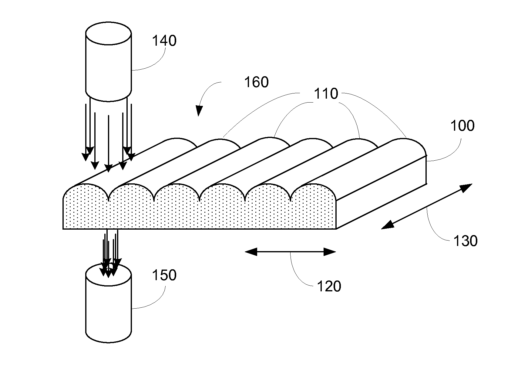
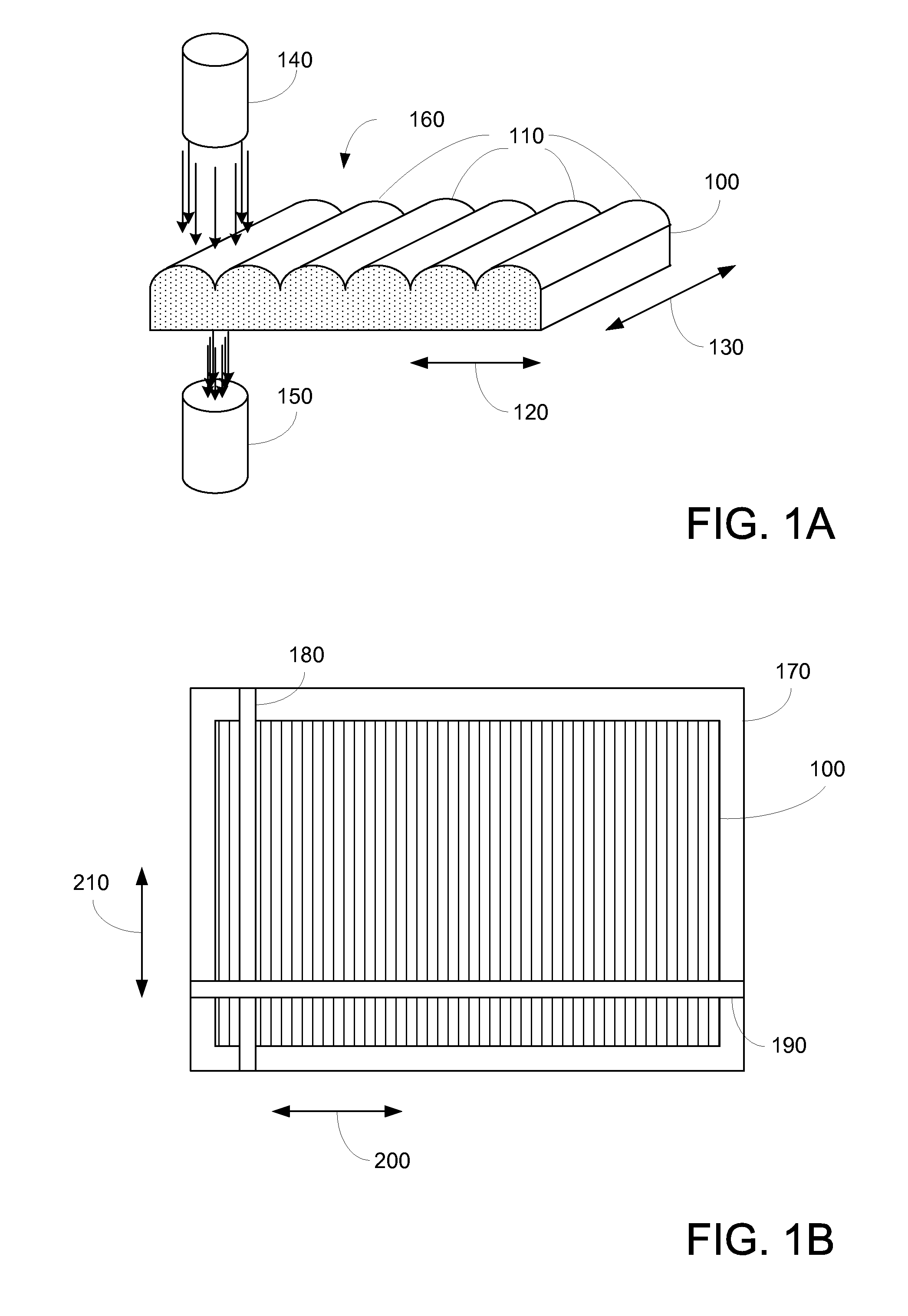
[0019]FIGS. 1A-B illustrate various aspects according to embodiments of the present invention. More specifically, FIGS. 1A-B illustrate apparatus for determining concentration characteristics of a sheet of material 100.

[0020]In FIG. 1A, an embodiment of a sheet of transparent / translucent material 100 is shown. As can be seen, sheet 100 may include a number of concentrating elements 110 in a first direction 120. In one example, there are approximately 175 concentrating elements across sheet 100, although in other examples, the number of concentrating elements may vary. In various examples, the nominal pitch of concentrating elements 110 ranges from approximately 5.5 mm to 6 mm.

[0021]In various embodiments, sheet 100 may be manufactured as a sheet of extruded material, accordingly, the concentrating elements may extend in a second direction 130, as shown. In other embodiments, the concentrating elements may vary in second direction 130.

[0022]In various embodiments of the present inven...


PUM

PropertyMeasurementUnit
temperatureaaaaaaaaaa
anglesaaaaaaaaaa
widthaaaaaaaaaa

Abstract

A method for forming a solar energy collection device includes receiving a sheet of glass comprising glass material, wherein the sheet of glass includes a plurality of light concentrating geometric features, measuring geometric characteristics for the plurality of light concentrating geometric features, mathematically calculating predicted light concentration characteristics for each of the plurality of light concentrating geometric features in response to the geometric characteristics, determining placement locations for a plurality of PV strips in response to the predicted light concentration characteristics for each of the plurality of light concentrating geometric features, and securing the plurality of PV strips relative to the sheet of glass in response to the placement locations for the plurality of PV strips.

Description

BACKGROUND OF THE INVENTION[0001]The present invention relates to photovoltaic energy sources. More particularly, the present invention relates to using photovoltaic (PV) strips to convert solar energy into electrical energy.[0002]The inventors of the present invention have determined that a challenge with using PV strips for capturing solar energy is how to effectively direct and concentrate incident light / radiation to PV strips. Another challenge is how to manufacture such concentrators with materials that can last the expected life span of a solar panel, or the like, e.g. over 20 years.[0003]One possible solution considered was with the use of a metal concentrator in front of a PV strip. Drawbacks to such solutions include that a metal concentrator would be bulky and would cause the thickness of the solar panel to increase greatly. Another drawback includes that exposed metal may corrode and lose reflecting capability as it ages.[0004]Another possible solution, considered by the ...

Claims


Application Information

Patent Timeline
Patent Type & Authority Patents(United States)
IPC IPC(8): B32B37/12
CPCB32B38/1808B32B41/00H01L31/0524H02S40/22H01L31/0543B32B2457/12B32B2038/1891Y02E10/52B32B38/1841
Inventor SHAH, SHIRISHMAGANA, FRANKFATEHI, JUNAIDCASAJE, ENRICOCHAWARE, RAGHUNANDAN
Owner SOLARIA CORP
Why Eureka
Try Eureka