Electric connecting apparatus

a technology of connecting apparatus and connecting plate, which is applied in the direction of electrical apparatus casing/cabinet/drawer, coupling device connection, instruments, etc., can solve the problems of increasing the heat generated by semiconductor devices, adversely affecting the enclosure or components disposed around the contact, and it is impossible for the contact holding plate to hold the contact, etc., to suppress the increase in the temperature of the electric connecting device. , the effect of high heat conductivity

Active Publication Date: 2013-01-29
YAMAICHI ELECTRONICS
View PDF17 Cites 5 Cited by
  • Summary
  • Abstract
  • Description
  • Claims
  • Application Information

AI Technical Summary

Benefits of technology

[0011]In the electric connecting apparatus according to the present invention, at least part of the housing that constitutes the electric connecting device is made of a material having high heat conductivity and the multiple contacts are arranged linearly in at least one row. Meanwhile, the multiple contacts are configured to come into abutting contact with the housing via at least an insulating member made of an electrically insulative material having high heat conductivity. Therefore, heat generated from each contact itself is dissipated effectively via the housing or via the housing and a printed wiring board on which the housing is mounted. In this way, it is possible to suppress an increase in temperature of the electric connecting device and thereby to prevent damages of components constituting the electric connecting apparatus.
[0012]Moreover, making an insulating plate of a material having high heat conductivity and simplifying a structure of the insulating plate enhance workability, thereby suppressing an increase in manufacturing cost of the electric connecting apparatus.

Problems solved by technology

An electric connecting apparatus configured to electrically connect a semiconductor device such as an integrated circuit package to a printed wiring board has had the following problem along with the complication of the configurations of semiconductor devices.
When current flows through a semiconductor device having such complicated configuration, an increasing amount of heat is generated from the semiconductor device.
This is because the heat generation from the contact itself may adversely affect an enclosure or components disposed around the contact.
In this case, it may become impossible for the contact holding plate to hold the contact.

Method used


Image

  • Electric connecting apparatus
  • Electric connecting apparatus
  • Electric connecting apparatus

Examples


first embodiment

(First Embodiment)

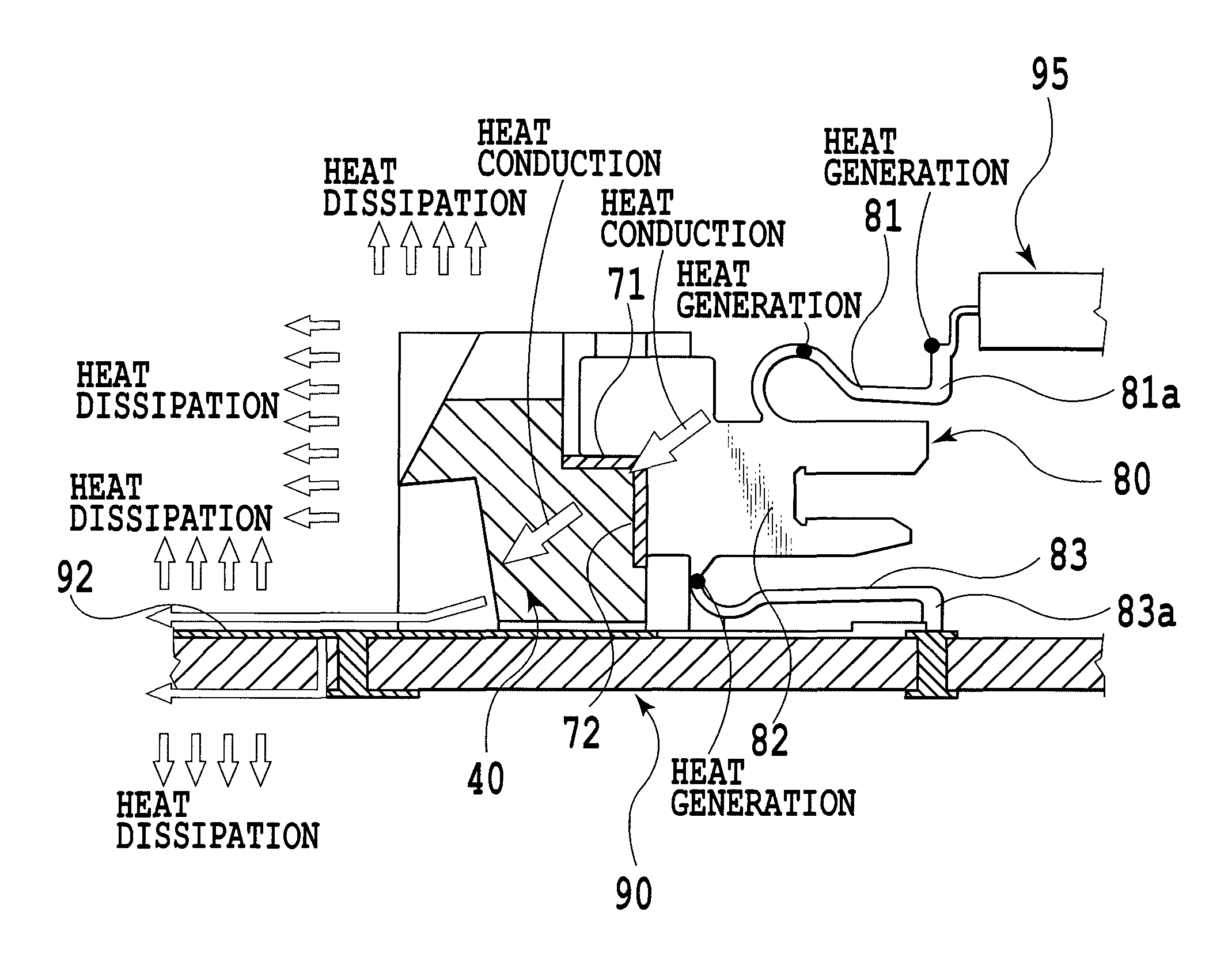
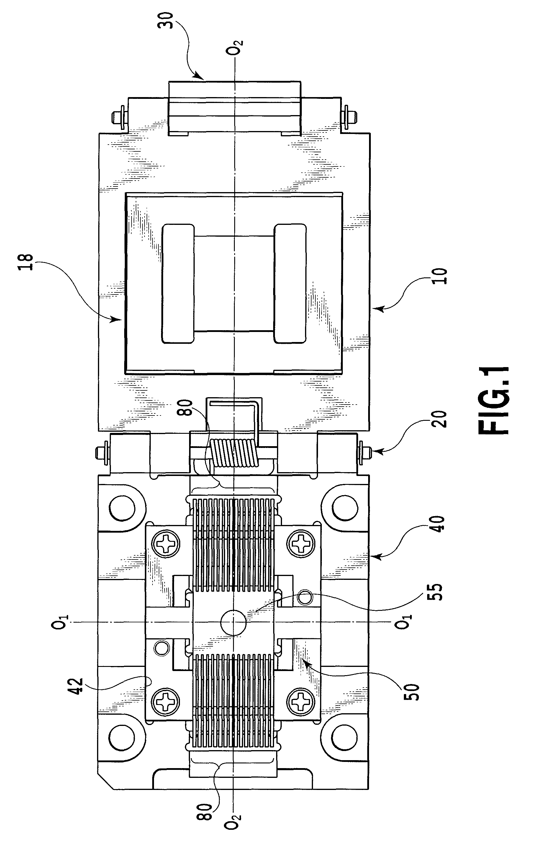
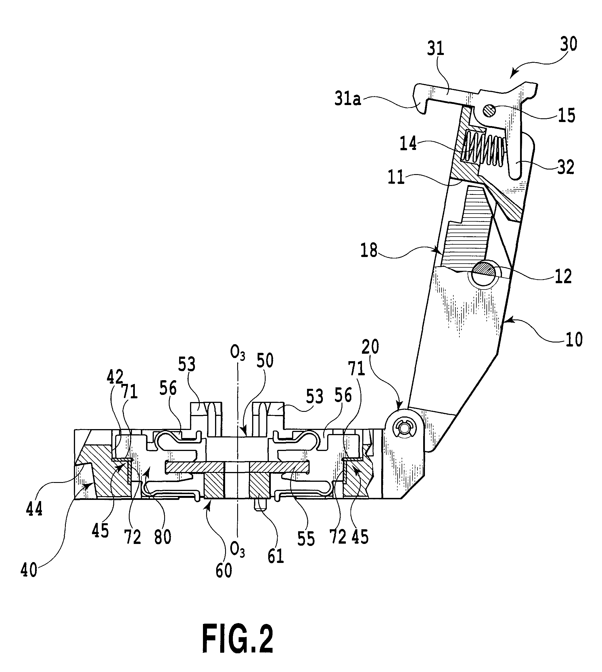
[0023]FIG. 1 to FIG. 5 show an electric connecting apparatus according to a first embodiment of the present invention. The electric connecting apparatus according to the first embodiment is shown as an IC socket of a clam shell type. Note that the electric connecting apparatus is not limited only to the one of the clam shell type but may also be the one of an open top type. The electric connecting apparatus according to this embodiment generally includes a cover member 10, a housing 40, and multiple contacts 80. For example, the electric connecting apparatus is mounted on a printed wiring board 90 such as a test board of a test instrument for testing a semiconductor device 95 (see FIG. 3). The semiconductor device 95 mounted on the electric connecting apparatus is electrically connected to the printed wiring board 90 via the contacts 80. In this embodiment, the semiconductor device 95 to be mounted is an integrated circuit package (hereinafter also referred to as a...

second embodiment

(Second Embodiment)

[0047]FIGS. 8A and 8B show an electric connecting apparatus according to a second embodiment of the present invention. The electric connecting apparatus according to the present embodiment is of a type in which multiple contacts are arranged in a matrix fashion.

[0048]FIGS. 8A and 8B show only a housing 110 of the electric connecting apparatus according to the present embodiment, which is configured to accommodate multiple contacts 150. The housing 110 essentially includes a main body portion 120 to accommodate the contacts 150, a contact holding member 130 made of synthetic resin being electrically insulative, a metallic base member 140, and the multiple contacts 150. As shown in FIG. 8A, the contacts 150 are arranged in a matrix fashion and the multiple contacts 150 are linearly arranged as in the case of the above-described first embodiment. Moreover, in the present embodiment, adjacent rows of the contacts 150 are arranged to be parallel to each other. Between ...


PUM


Abstract

Provided is an electric connecting apparatus configured to dissipate heat generated from a contact itself via an insulating plate, a metallic enclosure, and a printed wiring board. The electric connecting apparatus includes at least a housing configured to accommodate multiple contacts. At least part of the housing is made of a material having high heat conductivity. The multiple contacts are arranged linearly in at least one row. The multiple contacts are in abutting contact with the at least part of the housing via at least an insulating member made of an electrically insulative material having high heat conductivity.

Description

CROSS-REFERENCE TO RELATED APPLICATIONS[0001]This application claims the benefit of Japanese Patent Application No. 2009-207042, filed Sep. 8, 2009, which is hereby incorporated by reference herein in its entirety.BACKGROUND OF THE INVENTION[0002]1. Field of the Invention[0003]The present invention relates to an electric connecting apparatus for electrically connecting a semiconductor device and a printed wiring board, or more specifically to a heat dissipation mechanism of a contact constituting the electric connecting apparatus.[0004]2. Description of the Related Art[0005]An electric connecting apparatus configured to electrically connect a semiconductor device such as an integrated circuit package to a printed wiring board has had the following problem along with the complication of the configurations of semiconductor devices. When current flows through a semiconductor device having such complicated configuration, an increasing amount of heat is generated from the semiconductor d...

Claims


Application Information

Patent Timeline
Patent Type & Authority Patents(United States)
IPC IPC(8): H05K7/20
CPCG01R1/0458
Inventor KOBORI, EIJISUZUKI, TAKEYUKI
Owner YAMAICHI ELECTRONICS
Why Eureka
Try Eureka