Biodevice and contact part structure of biodevice

a biodevice and contact part technology, applied in the field of biodevices and contact part structures of biodevices, can solve the problems of large damage to the organism, inability to deny the possibility of the enzyme being displaced or the sensing parts becoming damaged, and the device being unsuitable for directly detecting and measuring inside the organism. , to achieve the effect of preventing the region from being damaged and the region very small

Inactive Publication Date: 2013-01-29
UNIVERSITY OF TOKUSHIMA
View PDF8 Cites 1 Cited by
  • Summary
  • Abstract
  • Description
  • Claims
  • Application Information

AI Technical Summary

Benefits of technology

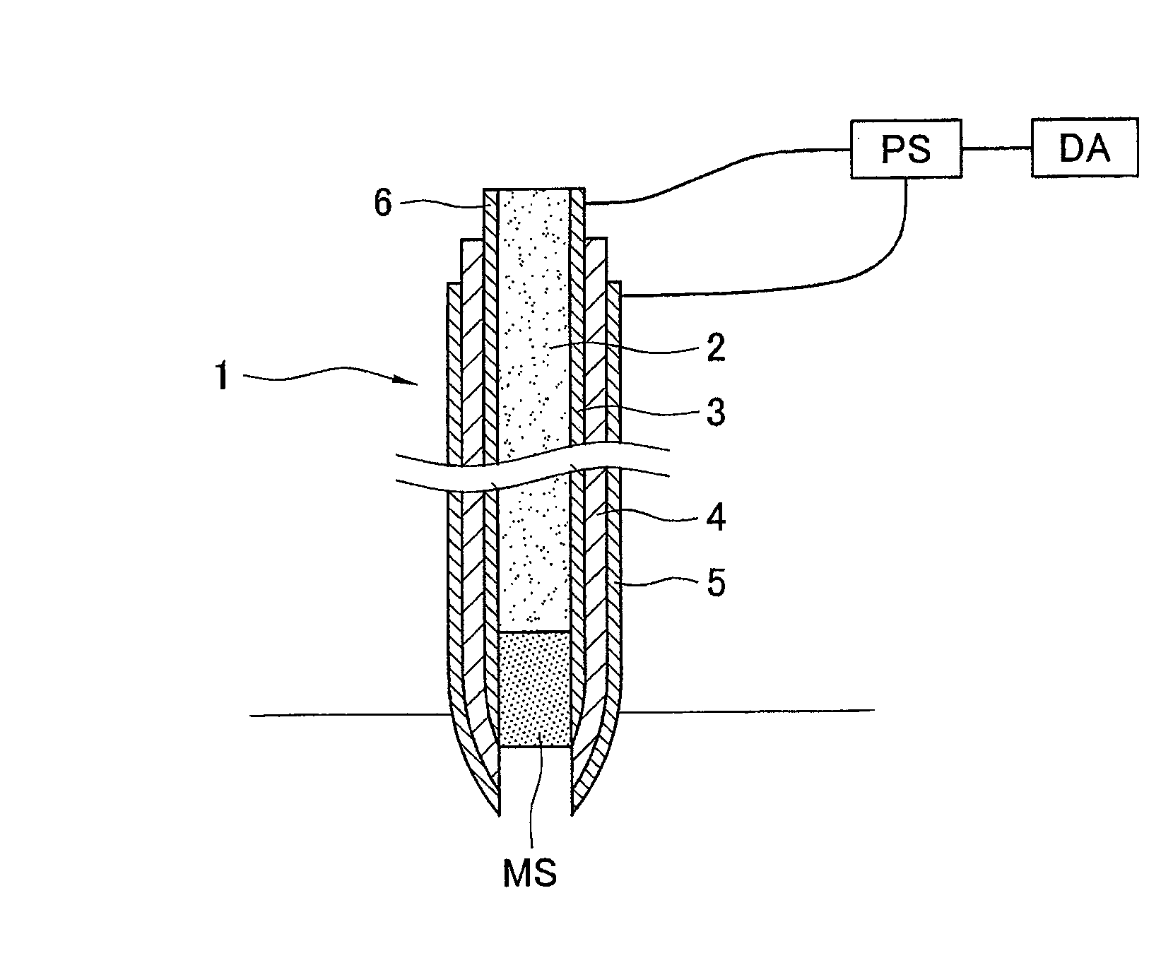
[0012]It is therefore an object of this invention, in view of the situation as described above, to provide a biosensor capable of directly detecting and measuring an object under test inside an organism by inserting or placing inside the organism and further of preventing the region being sensed from being damaged while keeping the region being sensed very small, as well as a biodevice usable for such a biosensor and a contact part structure of the biodevice.

Problems solved by technology

Since these devices have an electrode exposed to the surface and enzyme, etc. are attached to this electrode, one cannot deny the possibility of the enzyme becoming displaced or the sensing parts becoming damaged as the device is inserted into an organism.
Since the probe itself will become thick if the working electrode lead is made thick, however, the damage to the organism also becomes large when it is used to penetrate it or place inside.
Accordingly, this probe can be used for detecting an object under test inside a target object taken or separated from an organism but is not suitable for a device for directly detecting and measuring inside an organism without collecting any object under test inside the organism.
Although it would be very useful if it were possible to combine a biosensor in a treatment using an endoscope or a catheter used by inserting into an organism, such a biosensor allowing to be effectively combined to an endoscope or a catheter has not been developed and its development is being wished for.

Method used


Image

  • Biodevice and contact part structure of biodevice
  • Biodevice and contact part structure of biodevice
  • Biodevice and contact part structure of biodevice

Examples


Embodiment Construction

[0054]Embodiments of the invention are explained next with reference to the drawings.

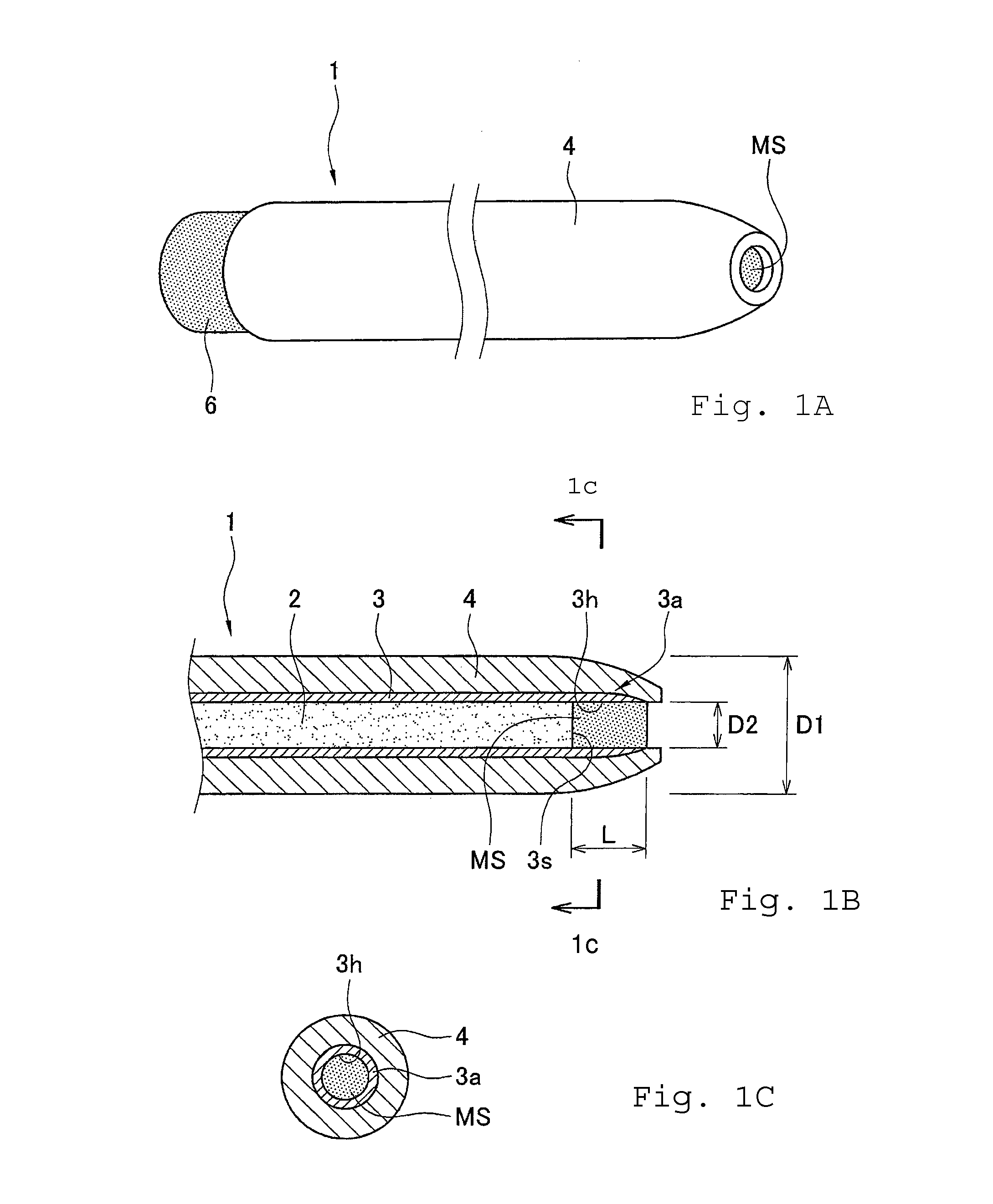
[0055]FIG. 1 is for schematically showing a rod-shaped device 1 which is one embodiment of the biodevice according to this invention, FIG. 1A being its schematic side view, FIG. 1B being a schematic enlarged view of its end and FIG. 1C being its sectional view taken long line IC-IC of FIG. 1B.

[0056]In the figures which are intended to make the structure of a biodevice and a biosensor easier to understand, the sizes and relative ratios of thickness and length of their components are not realistically represented. For the rod-shaped device 1 according to this invention shown in FIG. 1, if its outer diameter is about 0.3-500 μm, it is preferable that the outer diameter of its shaft member 2 be about 0.1-300 μm, the thickness of its conductive layer 3 be about 0.05-100 μm and the thickness of its insulating layer 4 be about 0.05-100 μm but the diameter of the shaft member 2 and the thicknesses of the co...


PUM

PropertyMeasurementUnit
diameteraaaaaaaaaa
diameteraaaaaaaaaa
diameteraaaaaaaaaa

Abstract

A biodevice is in an elongated form and has a conductive layer and an insulating layer stacked on a side surface of a shaft member at the center. A cylindrical hollow section is formed through the device, being connected to the exterior at a front end and extending from this front end axially. An electrode section is formed on an inner surface. A sensing substance such as enzyme may be placed at the electrode section to detect a current value corresponding to the concentration or quantity of an object under test placed between a counter electrode and the biodevice.

Description

[0001]This application is a continuation of International Application No. PCT / JP2007 / 052214, filed Feb. 8, 2007 which claims priority on Japanese Patent Applications 2006-032275 filed Feb. 9, 2006 and 2006-041358 files Feb. 17, 2006.BACKGROUND OF THE INVENTION[0002]This invention relates to biodevices and contact part structures of biodevices. A so-called enzyme sensor having a specified kind of enzyme attached to the surface of an electrode is used for measuring the concentration of sugar, amino acids, etc. in an organism. Such an sensor is used for making use of the characteristic of the enzyme attached to the electrode for singularly oxidizing or reducing sugar and amino acids to generate molecules and ions, and the concentration of sugar, amino acids, etc. can be measured by detecting the quantity of the generated molecules and ions as the value of the current that flows in the electrode. If the kind of the enzyme attached to the surface of the electrode is changed, furthermore,...

Claims


Application Information

Patent Timeline
Patent Type & Authority Patents(United States)
IPC IPC(8): A61B5/04C12M1/34
CPCA61B5/1411A61B5/14532A61B5/685A61B5/14865Y10T436/104998A61B5/150022A61B5/150236A61B5/150244A61B5/150282A61B5/150396A61B5/150427A61B5/150511A61B5/150977A61B5/151
Inventor YASUZAWA, MIKITOFURUKAWA, SHINYA
Owner UNIVERSITY OF TOKUSHIMA
Why Eureka
Try Eureka