Shower head and substrate processing apparatus

a technology of substrate and processing apparatus, which is applied in the direction of coatings, chemical vapor deposition coatings, electric discharge tubes, etc., can solve the problems of poor responsiveness, difficult to scale down the entire apparatus, and deterioration of in-plane uniform processing, so as to improve processing uniformity and control quickly and accurately

Active Publication Date: 2013-02-05
TOKYO ELECTRON LTD
View PDF49 Cites 19 Cited by
  • Summary
  • Abstract
  • Description
  • Claims
  • Application Information

AI Technical Summary

Benefits of technology

[0006]In view of the above, the present invention provides a shower head and a substrate processing apparatus capable of being scaled down and enabling a pressure in a processing chamber to be controlled quickly and accurately to thereby improve processing uniformity compared to prior arts.
[0021]The present invention can provide a shower head and a substrate processing apparatus, which can be scaled down and enable a pressure in a processing chamber to be controlled quickly and accurately to thereby improve processing uniformity compared to prior arts.

Problems solved by technology

Therefore, the gas supplied through the shower head flows from a central portion to a peripheral portion of the substrate, thereby making a processing state at the central portion of the substrate different from that at the peripheral portion of the substrate, resulting in deteriorating in-plane uniformity of the processing.
Further, a gas exhaust channel needs to be provided at a periphery of the mounting table (substrate) or that of the shower head, so that the processing chamber is considerably scaled up compared to the substrate accommodated therein, which makes it difficult to scale down the entire apparatus.
As a result, responsiveness becomes poor, or fine adjustment becomes difficult.

Method used


Image

  • Shower head and substrate processing apparatus
  • Shower head and substrate processing apparatus
  • Shower head and substrate processing apparatus

Examples


second embodiment

[0056]FIG. 4 shows a configuration of a shower head 100a in accordance with the present invention. In this shower head 100a, second gas injection openings 21a are formed through the intermediate member 2 and the lower member 1 to open toward the substrate, and the second gas is supplied through the second gas injection openings 21a toward the substrate. The configurations of other parts are the same as those of the embodiment shown in FIG. 1.

[0057]In the shower head 100a configured as described above, either the pressure control gas such as N2 gas or a processing gas for use in processing the substrate can be supplied as the second gas supplied through the second gas injection openings 21a. In the case of supplying a processing gas as the second gas, a processing gas can be supplied as the second gas at the same time when a processing gas of different species is supplied through the first gas injection openings 11. Alternatively, a processing gas for pre- or post-process can also be...

third embodiment

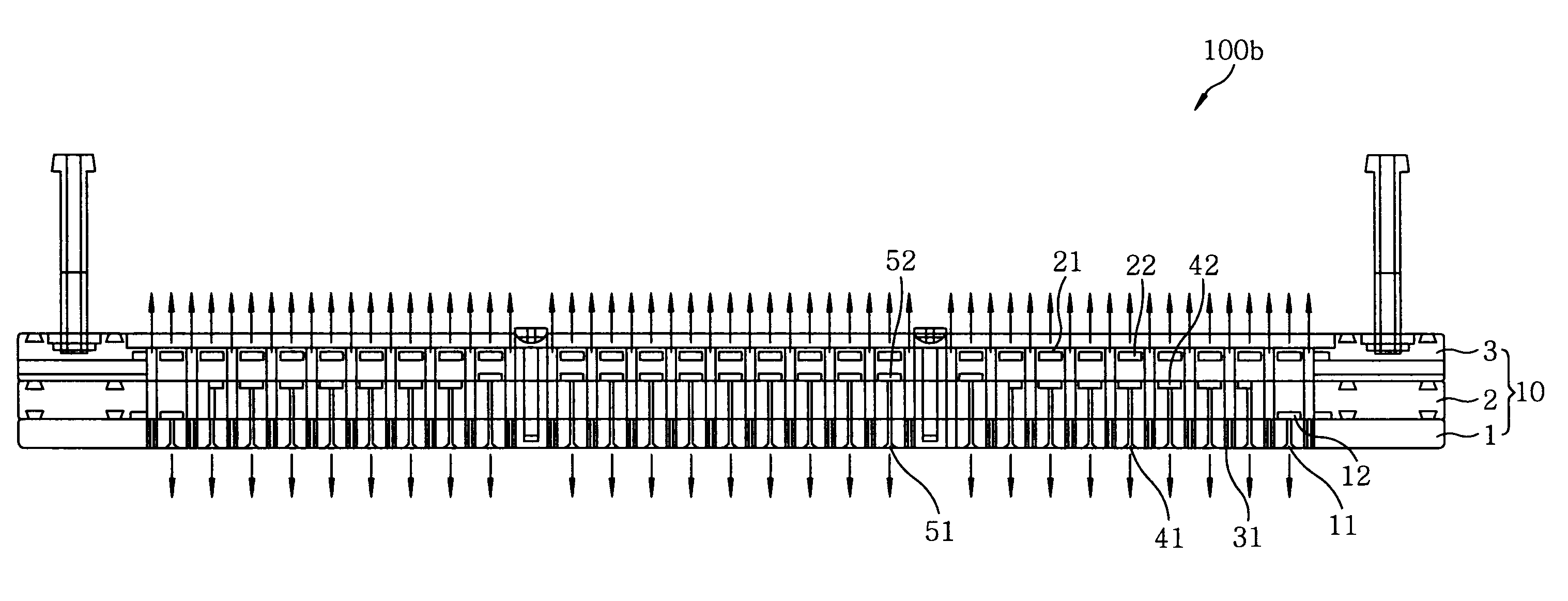
[0061]FIG. 6 shows a configuration of a shower head 100b in accordance with the present invention. This shower head 100b includes, in addition to the first and the second gas injection openings 11 and 21 of the shower head 100, third gas injection openings 41 for supplying a third gas and fourth gas injection openings 51 for supplying a fourth gas. Accordingly, respective gases can be supplied from the first, the third and the fourth gas injection openings 11, 41 and 51 to three different regions on the substrate (lower side of FIG. 6).

[0062]That is, in the shower head 100b, the first gas injection openings 11 are formed at a peripheral portion, and communicate with the first gas channel 12 formed between the lower member 1 and the intermediate member 2, thus supplying the first gas to the peripheral region of the substrate. Moreover, the third gas injection openings 41 are formed at an intermediate portion between a central portion and the peripheral portion, and communicate with t...

first embodiment

[0065]FIG. 7 presents a simulation result of a gas flow in the shower head 100 of the FIG. 8 represents a simulation result of a vertical cross sectional pressure distribution. Meanwhile, FIGS. 9 and 10 illustrate a result of the same simulation carried out in a conventional shower head in which a gas is supplied from the shower head and exhausted through the lower portion of a processing chamber. Referring to FIGS. 8 and 10, pressure ranges of varying magnitudes are represented by different types of hatchings shown in the left sides of the drawings. Therefore, the pressure distribution becomes more uniform as a smaller number of different hatchings are presented in partial areas of the chamber shown in the right sides of the drawings.

[0066]When FIG. 7 is compared with FIG. 9, it is clear that, in a conventional shower head, a gas flow line becomes long and, thus, the gas supplied to the vicinity of the central portion of the substrate transverses the substrate surface and reaches ...


PUM

PropertyMeasurementUnit
diameteraaaaaaaaaa
diameteraaaaaaaaaa
frequencyaaaaaaaaaa

Abstract

A shower head is provided in a processing chamber for processing a substrate therein to face a mounting table for mounting thereon the substrate and formed of a laminated body in which a plurality of plate-shaped members are laminated. The shower head serves to supply one or more gases in a shower shape toward the substrate. The shower head includes a first gas supply unit for supplying a first gas toward the substrate through first gas injection openings provided in the laminated body, a second gas supply unit for supplying a second gas through second gas injection openings provided in the laminated body and a plurality of gas exhaust holes, formed through the laminated body, for exhausting a gas through a portion of the laminated body, the portion facing the mounting table.

Description

FIELD OF THE INVENTION[0001]The present invention relates to a shower head and a substrate processing apparatus which are used for plasma processing of a substrate or the like.BACKGROUND OF THE INVENTION[0002]Conventionally, in, e.g., a manufacturing process of a semiconductor device, a substrate processing apparatus for processing a substrate while supplying a gas in a shower shape through a shower head disposed to face a substrate has been used as a processing apparatus for processing a substrate such as a semiconductor wafer or a glass substrate for use in a liquid crystal display or the like.[0003]For example, in a plasma processing apparatus for performing plasma processing such as an etching process or a film forming process on a substrate disposed in a processing chamber by using a plasma generated from a processing gas in the processing chamber, the shower head forms an electrode facing a mounting table for mounting thereon the substrate. Further, a predetermined processing ...

Claims


Application Information

Patent Timeline
Patent Type & Authority Patents(United States)
IPC IPC(8): C23C16/455H01L21/306C23C16/00C23C16/52C23C16/22C23C16/06
CPCC23C16/4412C23C16/45565H01J37/32449H01J37/3244C23C16/45574H01L21/3065H01L21/205C23C16/455
Inventor IIZUKA, HACHISHIRO
Owner TOKYO ELECTRON LTD
Why Eureka
Try Eureka