Polyphase electrical machine

a technology of electrical machines and polyphase, applied in the direction of dynamo-electric machines, electrical apparatus, magnetic circuits, etc., can solve the problems of high manufacturing tolerance limits, achieve the effects of reducing the ripple of unidirectional generator voltage, reducing the noise of magnetic flux and flow, and improving power output and efficiency factor

Active Publication Date: 2013-02-05
SEG AUTOMOTIVE GERMANY GMBH
View PDF20 Cites 18 Cited by
  • Summary
  • Abstract
  • Description
  • Claims
  • Application Information

AI Technical Summary

Benefits of technology

[0003]In the polyphase electrical machine built according to the present invention, it is provided that in the stator, each winding and each slot of a group of slots that extends over one pole pitch is assigned to one of the phases, and the windings have winding sections that lie in assigned slots and between which, in each case, a winding-head connection is formed, the winding-head connections of different windings being disposed radially in layers relative to each other, and the number of phases being five. Such a setup has an advantage that both the magnetic noise and the flow-generated noise are reduced. A further advantage is that the ripple of the unidirectional generator voltage decreases, and power output and the efficiency factor are thereby improved. Another benefit is that one may take advantage of the simple design of the machine to employ a cost-effective manufacturing method, and in so doing, to obtain an even better construction quality. For example, prefabricated windings are used to form a winding configuration of the electrical machine according to the present invention. The windings may be produced by machine and mounted, e.g., inserted, pulled in or slipped into the core body (the stator iron) by machine. The windings are disposed radially and layered with respect to each other in the circumferential direction. A five-phase electrical machine allows a larger wire diameter compared to an electrical machine having a two times three-phase system or a six-phase electrical machine, since when working with the same stator diameter, the smaller number of slots results in a larger slot area, given a correspondingly identical number of poles and winding connections. Due to the larger wire diameter, the robustness and mechanical loading capability of the electrical machine are higher. Moreover, the smaller number of slots allows higher manufacturing tolerance limits. At the same time, the acoustic behavior of a five-phase electrical machine is more favorable than for a three-phase electrical machine. Radial position is to be understood as the exact position in the radial direction for the winding in the winding heads.

Problems solved by technology

Moreover, the smaller number of slots allows higher manufacturing tolerance limits.

Method used


Image

  • Polyphase electrical machine
  • Polyphase electrical machine
  • Polyphase electrical machine

Examples


Embodiment Construction

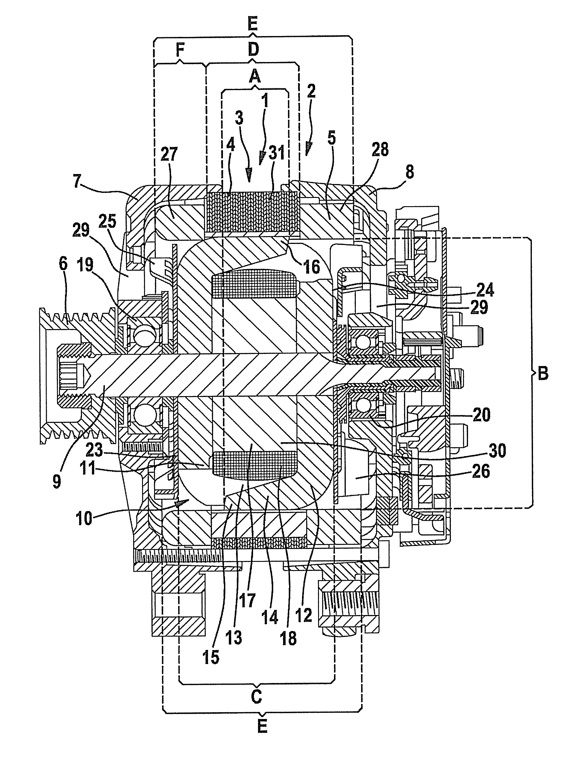
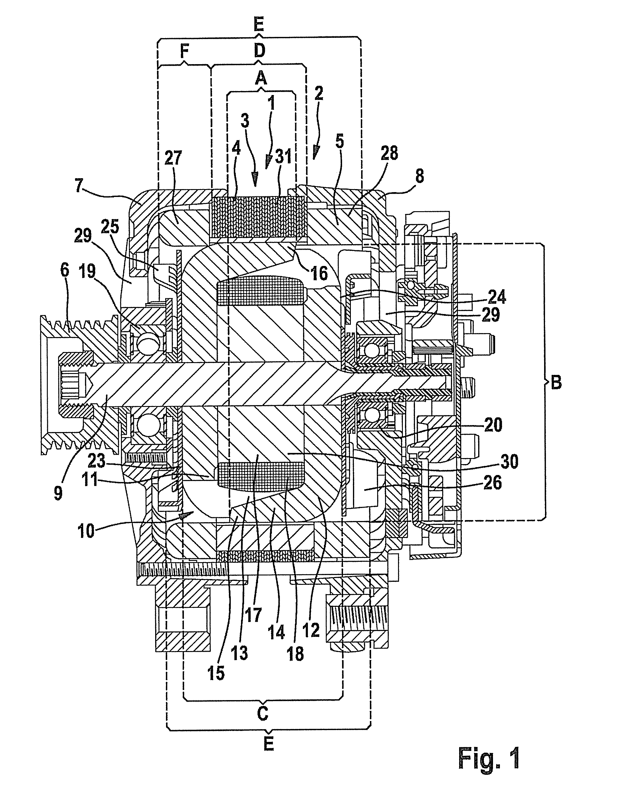
[0066]FIG. 1 shows a polyphase electrical machine 2 taking the form of generator 1 as used, for example, in motor vehicles. Electrical machine 2 has a stator 3 having a core body 4 and a winding configuration 5. Stator 3 is supported by two brackets—a drive-end bracket 7 facing belt pulley 6 and a slip-ring-end bracket 8. Stator 3 radially surrounds a rotor 10 disposed on a shaft 9. Rotor 10 has two claw-pole plate bars at whose periphery essentially trapezoidal claw fingers 13, 14 are disposed, in each case extending in the axial direction. Both claw-pole plate bars are disposed in the rotor in such a way that their axially extending claw fingers mesh and alternate with each other as north pole and south pole at the periphery of the rotor. Magnetically necessary claw-pole interspaces are thereby obtained between the inversely magnetized claw fingers, lying opposite each other in the circumferential direction. Claw fingertips 15, 16 of claw fingers 13, 14 opposite each other in the ...


PUM

PropertyMeasurementUnit
phase angleaaaaaaaaaa
diameteraaaaaaaaaa
slot widthaaaaaaaaaa

Abstract

A polyphase electrical machine, in particular, a polyphase generator, includes a stator which features a core body having a circumferential slot pitch, and a winding configuration having a plurality of windings. It is provided that each winding and each slot of the group of slots that extends over one pole pitch is assigned to one of the phases, and the windings have winding sections that lie in assigned slots and between which, in each case, a winding-head connection is formed, the winding-head connections of different windings being disposed radially in layers relative to each other, and the number of phases being five. A method for producing a polyphase electrical machine is also provided.

Description

FIELD OF INVENTION[0001]The present invention relates to a polyphase electrical machine, in particular, a polyphase generator, having a stator which features a core body having a circumferential slot pitch, and a winding configuration having a plurality of windings forming phases. The present invention also relates to a method for producing a corresponding polyphase electrical machine.BACKGROUND INFORMATION[0002]A polyphase electrical machine of the type indicated at the outset is known, for example, as an alternating-current generator. This alternating-current generator has a stator having a core body (stator iron) in the form of a laminated stator core, into slots of which, windings for three, two times three or six phases are inserted. The windings are staggered relative to each other. In the case of a three-phase generator, an unwanted magnetic noise develops due to electromagnetic forces. To reduce this magnetic noise, special winding configurations are provided which, for exam...

Claims


Application Information

Patent Timeline
Patent Type & Authority Patents(United States)
IPC IPC(8): H02K1/00
CPCH02K3/28H02K15/0442Y10T29/49009
Inventor WOLF, GERTPFITZKE, NORBERTBERGER, THOMASRAU, EBERHARDSHENDI, ALEXANDER
Owner SEG AUTOMOTIVE GERMANY GMBH
Why Eureka
Try Eureka