Bicycle power meter with frame mounted sensor

a frame mounted sensor and power meter technology, applied in the direction of force/torque/work measurement apparatus, cycle equipment, instruments, etc., can solve the problems of not finding wide acceptance in the bicycling community, bicycle power meters using strain gauges are relatively expensive, and difficult to install, etc., to facilitate the inclusion of a bicycle power meter, easy to secure, and low cost and effort

Active Publication Date: 2013-02-05
SILICON VALLEY MICRO C
View PDF7 Cites 12 Cited by
  • Summary
  • Abstract
  • Description
  • Claims
  • Application Information

AI Technical Summary

Benefits of technology

[0011]The invention greatly facilitates the inclusion of a bicycle power meter with any bicycle having a relatively compressible structural portion at the end of the rear fork of the bicycle frame. The entire power meter system, or just the strain gauge sensor assemblies, can be easily secured to the bicycle components at the point of manufacture. Similarly, the entire system can be readily secured to the bicycle at any point in the distribution chain, such as at the retailer as an add-on option. The bicyclist can also add the bicycle power meter system to a bicycle after purchase, at relatively low cost and effort.

Problems solved by technology

While effective in providing electrical signals representative of applied force, known bicycle power meters using strain gauges are relatively expensive and somewhat difficult to install.
Due to these disadvantages, bicycle power meters have not found wide acceptance in the bicycling community.

Method used


Image

  • Bicycle power meter with frame mounted sensor
  • Bicycle power meter with frame mounted sensor
  • Bicycle power meter with frame mounted sensor

Examples


first embodiment

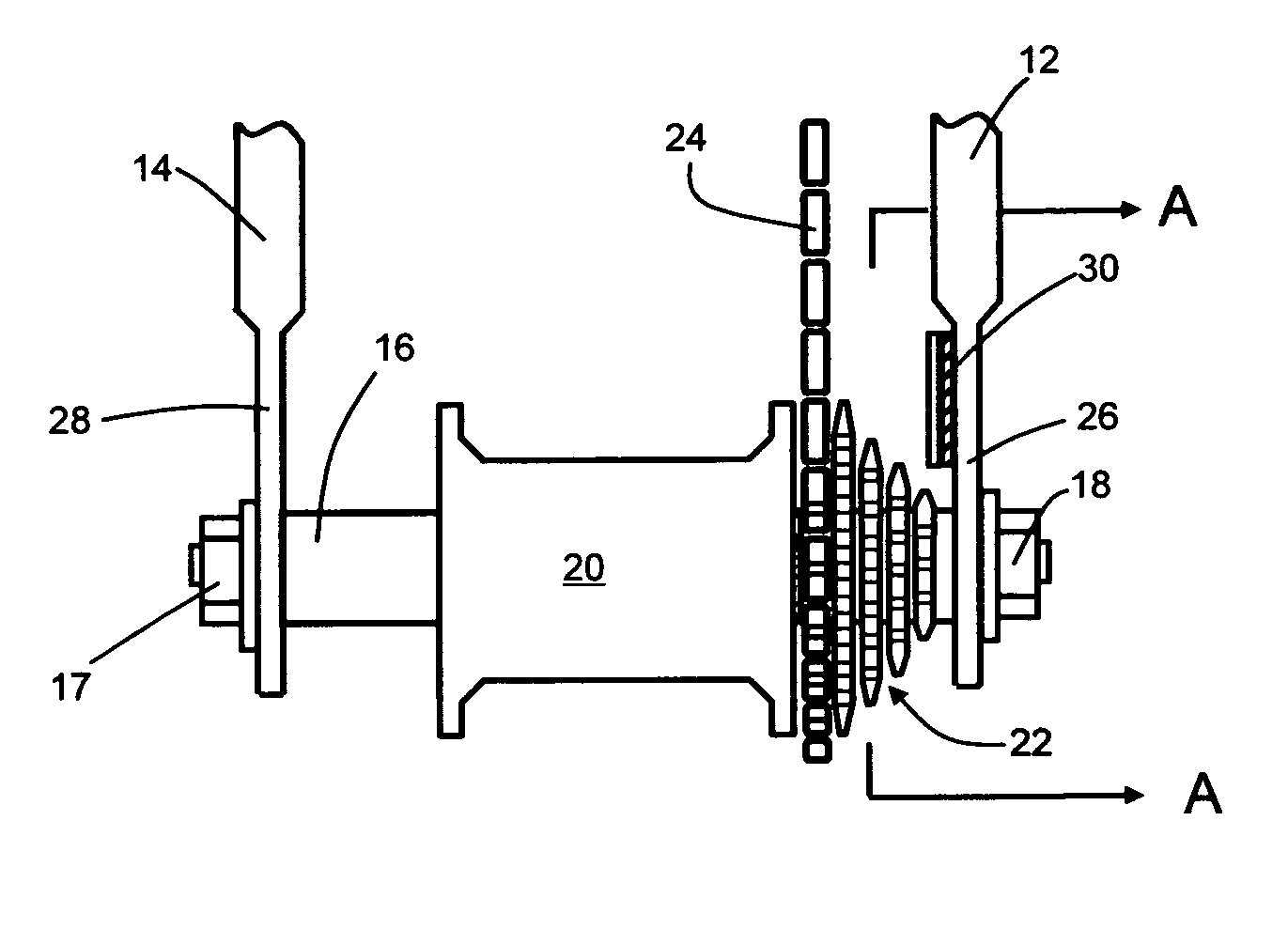
[0025]Turning now to the drawings, FIG. 1 is a perspective partial view taken from above of a bicycle rear frame illustrating the fork ends, hub, chain and strain gauge sensor assembly of the invention. As seen in this Fig., a bicycle rear frame has a pair of terminating portions termed a right fork 12 and a left fork 14. Secured between forks 12, 14 by means of an axle 16 and capture nuts 17, 18 are a rear hub 20 and a sprocket assembly 22. A drive chain 24 passes around individual sprockets comprising sprocket assembly 22 in order to provide rotational movement of hub 20 is response to cycling effort by the cyclist.

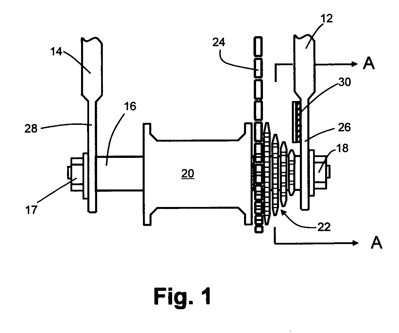
[0026]The end portion 26, 28 of each of forks 12, 14 has a thinner lateral thickness dimension than the remaining major portion of each fork 12, 14. Secured to the inner surface of end portion 26 of right fork 12 is a strain gauge sensor assembly 30 described more fully below. As best shown in FIG. 2, strain gauge sensor assembly 30 is attached to a thin web portion 32 ...

second embodiment

[0033]FIG. 8 is a perspective partial view taken from above of a bicycle rear frame illustrating the fork ends, hub, chain and strain gauge sensor assembly of the invention having two separate strain gauge sensor assemblies. In this Fig., elements corresponding to the same elements shown in FIG. 1 are designated with the same reference numerals, with the exception of sensor assembly 30 which is designated with reference 30a. Secured to the inner surface of end portion 28 of left fork 14 is a second strain gauge sensor assembly 30b. Sensor assembly 30b has the same structure and function as sensor assembly 30 described above. As best shown in FIG. 9, strain gauge sensor assembly 30b is attached to a thin web portion 33 extending along end portion 28 of left fork 14. Web portion 33 has the mechanical property of being relatively compressible when compared to the more robust structure of left rear fork 14, so that the physical dimensions of strain gauge sensor assembly 30b can change w...


PUM

PropertyMeasurementUnit
thicknessaaaaaaaaaa
resistanceaaaaaaaaaa
fixed resistancesaaaaaaaaaa

Abstract

A bicycle power meter has a strain gauge sensor assembly mounted on a relatively compressible portion of the end of the rear fork of the bicycle frame. The relatively compressible portion is near the rear hub and subject to the forces exerted by the cyclist to the crankset, and transferred via the chain, and sprocket assembly to the hub. The sensor assembly has two ohmically interconnected stretch sensors each having a first layer bearing a variable resistance element, whose resistance changes with displacement of the compressible portion, and a second layer for providing support for the first layer. The sensor assembly is connected in a bridge circuit to two other resistances to generate signals representative of cyclist applied force. These signals are processed along with velocity signals to generate power signals and the power signals are supplied to a display.

Description

BACKGROUND OF THE INVENTION[0001]This invention relates to bicycle power meters used to indicate the amount of power expended by the bicyclist during cycling. More particularly, this invention relates to a bicycle power meter using a frame mounted sensor for enabling the generation of electrical signals from which power can be determined.[0002]Bicycle power meters are being increasingly used by both professional and amateur cyclists as an aid in developmental training. Several different types of bicycle power meters are available, some of which use strain gauges to measure the force applied by the cyclist to the crankset, the bottom bracket or the rear wheel hub. While effective in providing electrical signals representative of applied force, known bicycle power meters using strain gauges are relatively expensive and somewhat difficult to install. Due to these disadvantages, bicycle power meters have not found wide acceptance in the bicycling community.SUMMARY OF THE INVENTION[0003]...

Claims


Application Information

Patent Timeline
Patent Type & Authority Patents(United States)
IPC IPC(8): G01L1/00
CPCG01L1/2256G01L5/0095G01L1/22B62J2099/002A61B5/1118B62K2207/00A61B5/6895B62J45/41B62J45/42
Inventor ZHU, SHENGBOHUANG, SU SHIONG
Owner SILICON VALLEY MICRO C
Why Eureka
Try Eureka