
Smart food chopper

a technology of food chopper and cutting blade, which is applied in the field of food preparation devices, can solve the problems of not being able to chop vegetables with stiff skin or outer layer, vegetables that are too soft or hard, and not being able to cut vegetables in an easy and efficient manner, and achieves the effect of not being able to chop vegetables completely, avoiding the chopping of outer stiff layer, and avoiding chopping of vegetables

Active Publication Date: 2013-02-12
GHIMIRE SHANKAR RAJ
View PDF7 Cites 4 Cited by
  • Summary
  • Abstract
  • Description
  • Claims
  • Application Information

AI Technical Summary

Benefits of technology

The invention provides blade sets that can move in a lateral reciprocal direction and are orthogonally configured. The blades have parallel cutting edges and are supported on both sides by two frames. The blade sets can be controlled by a controller that receives a force or pressure signal from a sensor and adjusts the speed of the motor accordingly to provide smooth and controlled chopping of the food. The blade sets can also be adjusted vertically and planarly for easy adjustment. A lid can be provided to help the food pass through the blade sets. The technical effects of the invention include improved chopping efficiency, smooth and controlled chopping, and easy adjustment of the blade sets.

Problems solved by technology

There are other specially designed devices for chopping foods, but none is particularly well suited for chopping onion, tomato etc. in an easy and efficient manner.
This device can not slice the vegetables with stiff skin or outer layer, or the vegetables that are too soft or hard, in an efficient manner.
In such devices, during the process of chopping, outer stiffer layer gets stuck on the grid and vegetables can not be chopped completely.

Method used


Image

  • Smart food chopper
  • Smart food chopper
  • Smart food chopper

Examples


Embodiment Construction

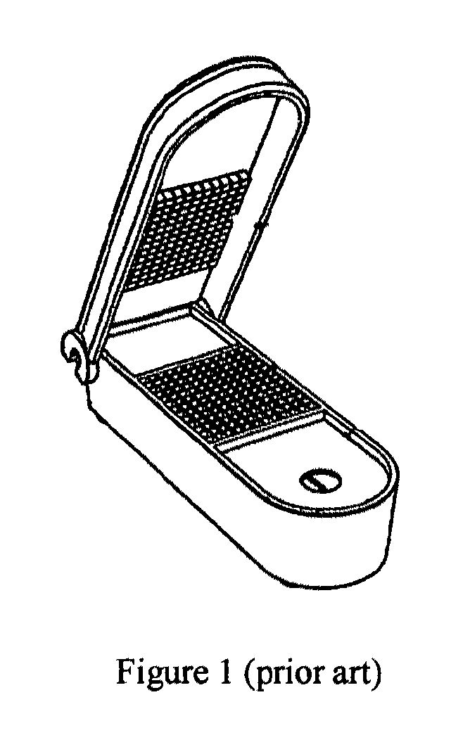
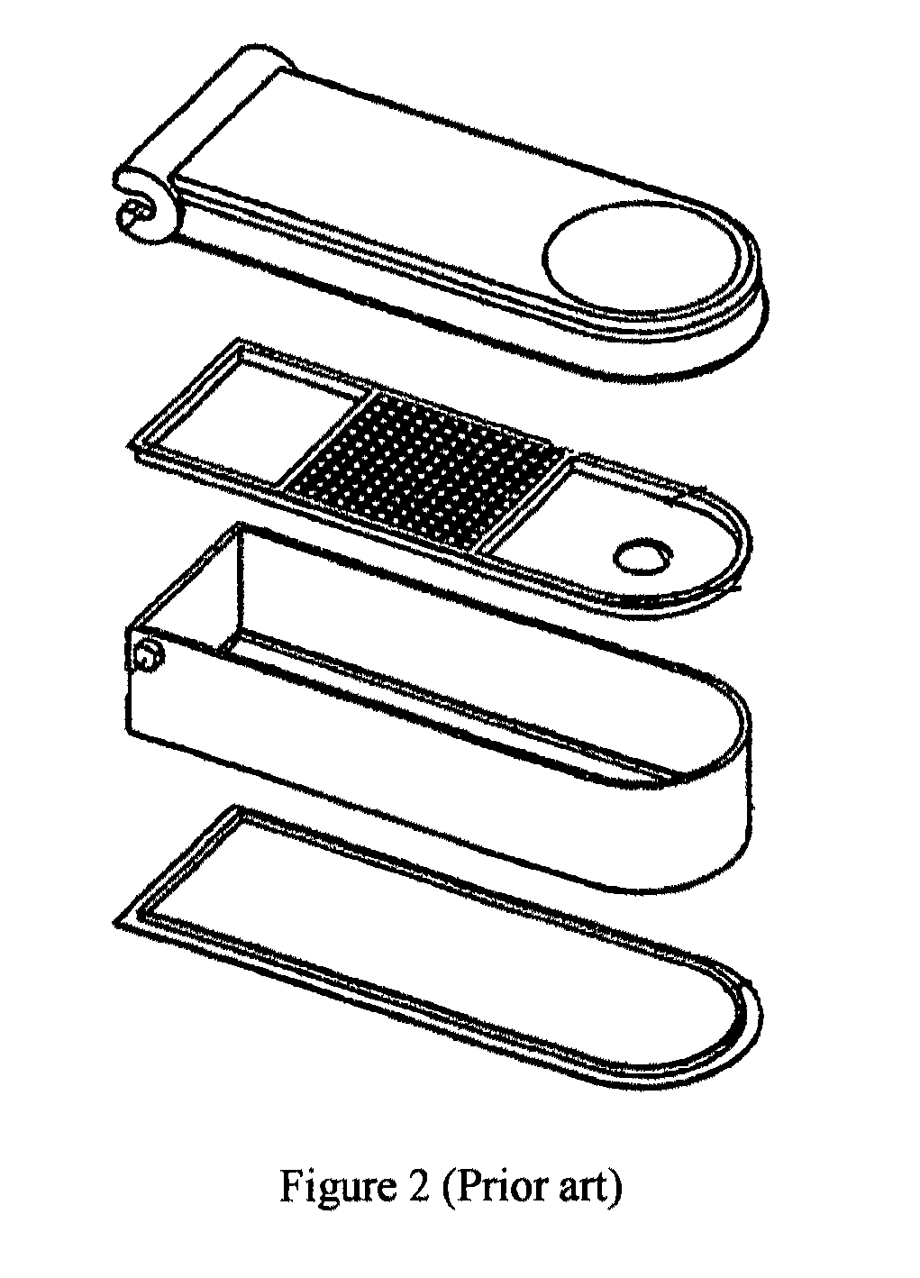
[0049]FIGS. 1 and 2 show the various embodiments of the prior art (U.S. 2007 / 0125217 A1). Blade 40 of the prior art is immovable. The prior art device require high pressure to onset the cutting process and chop off the food and vegetables. Use of such devices result in squashing of the food and vegetables. In some cases, the solid and liquid part of the vegetables may also be separated. The use of such devices may change the overall integrity of the food and vegetables. Prior art provide no means to overcome this problem.

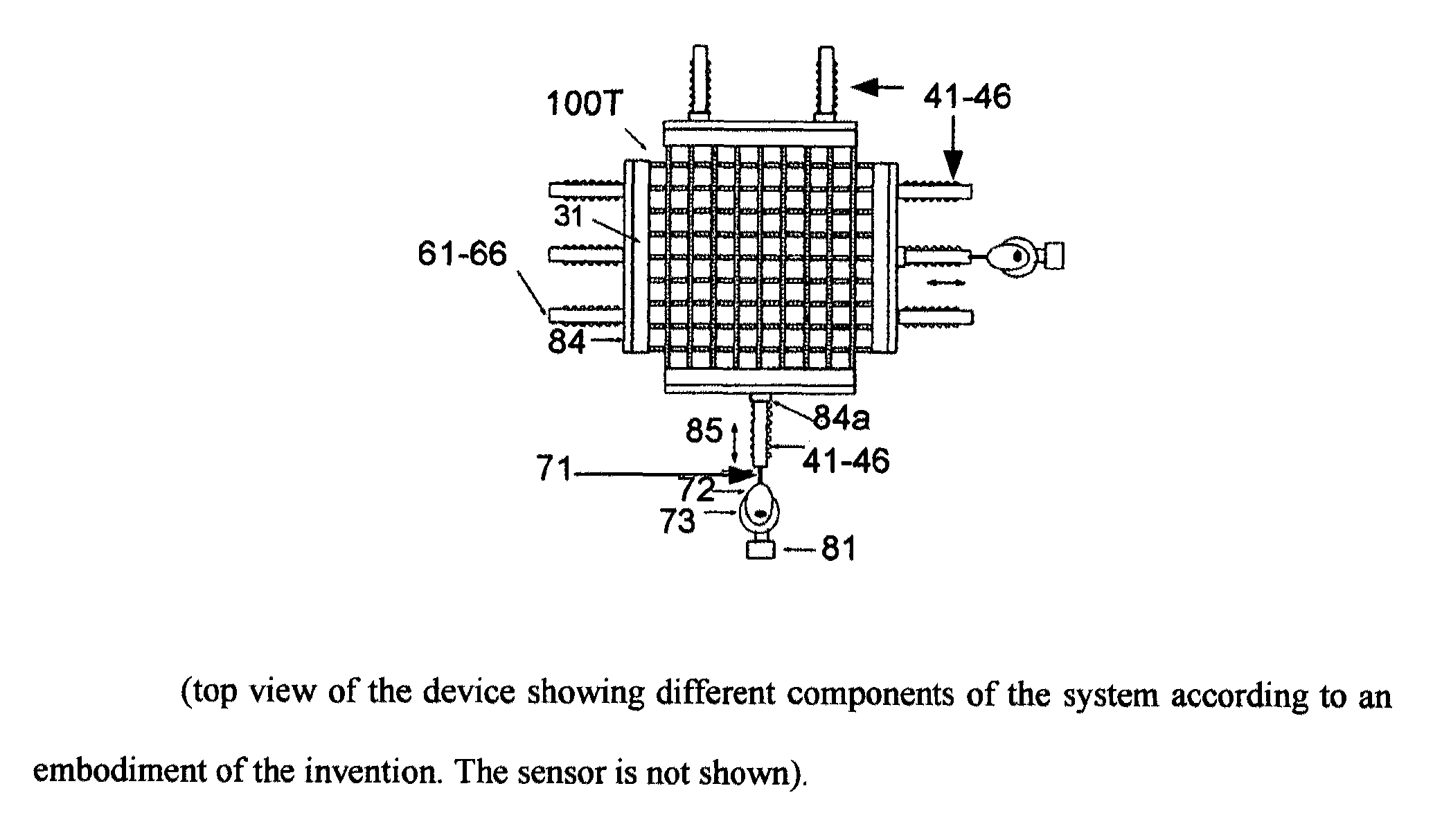
[0050]FIGS. 3-21 illustrate a noble system and method of chopping foods and vegetables according to an embodiment of the present invention by providing blade sets that are moveable and are orthogonally configured. Each blade sets include parallel blades that are supported by a frame on opposing sides (FIG. 3). Each blade are equally spaced and are parallel with one another (FIGS. 4-13). Each blade have rectangular or U-shaped cut outs that are periodic along the len...


PUM

PropertyMeasurementUnit
thicknessaaaaaaaaaa
thicknessaaaaaaaaaa
thicknessaaaaaaaaaa

Abstract

A smart food chopping or slicing device comprising at least two moveable blade sets arranged in a grid like configuration wherein the blade sets are configured orthogonally such that the cutting edges of both the blade sets remain substantially in the same plane. The movement of one set of blades is independent of the movement of another set of blades and can be independently controlled. The moveable blade sets are configured for lateral reciprocal movement. The plane of the lateral reciprocal movement of the cutting edges of the blade sets and the plane of the cutting edges of the blade sets are substantially the same or the same parallel planes. The blade sets are removeably mounted on a means capable of providing lateral reciprocal movement to the blade sets.

Description

CROSS REFERENCE TO RELATED APPLICATIONS[0001]This application claims priority under 35 USC 119(e) (1) of U.S. Provisional Patent Application Ser. No. 61 / 125,551 filed on Apr. 25, 2008.FIELD OF THE INVENTION[0002]This invention relates generally to food preparation devices, including devices for chopping or slicing onions, tomatoes, potatoes, mushroom, carrots, and the like.BACKGROUND OF THE INVENTION[0003]In preparing food it is often required to slice vegetables such as onion, potato, or tomato into small pieces. Most commonly, this is done by using knife. There are other specially designed devices for chopping foods, but none is particularly well suited for chopping onion, tomato etc. in an easy and efficient manner.[0004]One exemplary and specially designed device for chopping onions, potato, tomato etc. includes an array of rectangular projections that can be pressed downward to push the food and vegetables through a grid of blades (see U.S. patent application publication 2007 / 0...

Claims


Application Information

Patent Timeline
Patent Type & Authority Patents(United States)
IPC IPC(8): B26D1/06
CPCB26D3/20B26D3/26B26D5/00B26D7/00B26D3/185B26D5/16B26D2210/02Y10T83/222Y10T83/6895Y10T83/8828Y10T83/9454
Inventor GHIMIRE, SHANKAR RAJ
Owner GHIMIRE SHANKAR RAJ
Learn More