
Method and apparatus for using power-line phase-cut signaling to change energy usage

a technology of phase-cut signaling and powerline, which is applied in the direction of electric devices, data processing applications, process and machine control, etc., can solve the problems of insufficient power generation capacity, low infrastructure cost, and the cost of automatically forwarding this signal to “sheddable” loads at each customer site, so as to reduce energy usage, reduce energy usage, and minimize additional wiring

Active Publication Date: 2013-02-12
BENYA LIGHTING DESIGN +2
View PDF12 Cites 38 Cited by
  • Summary
  • Abstract
  • Description
  • Claims
  • Application Information

AI Technical Summary

Benefits of technology

This approach enables efficient distribution of demand-response signals to individual devices, reducing energy usage during peak periods while minimizing infrastructure changes and costs, ensuring reliable power management without overloading the grid.

Problems solved by technology

This can be a problem, because there may not exist sufficient power-generation capacity to handle peak energy requirements.
While sending such a signal to customers involves low infrastructure cost, automatically forwarding this signal to “sheddable” loads at each customer site can involve considerable cost.
For instance, in most buildings, existing building automation and energy-control systems lack cannot shed individual loads or categories of loads, and adding such capabilities typically involves expensive rewiring.
Alternative technologies, such as wireless mesh networks that use cellular and radio-frequency signals, can be used, but these alternative technologies typically require expensive hardware to be added to every device that receives the signal.

Method used


Image

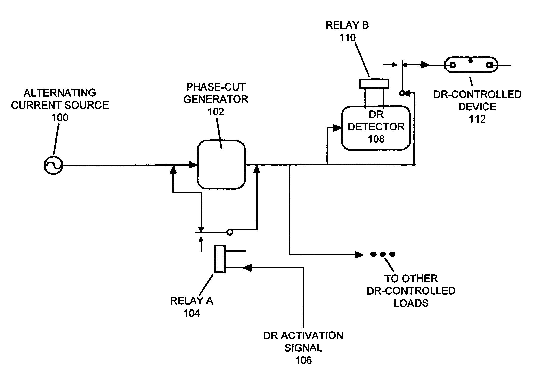
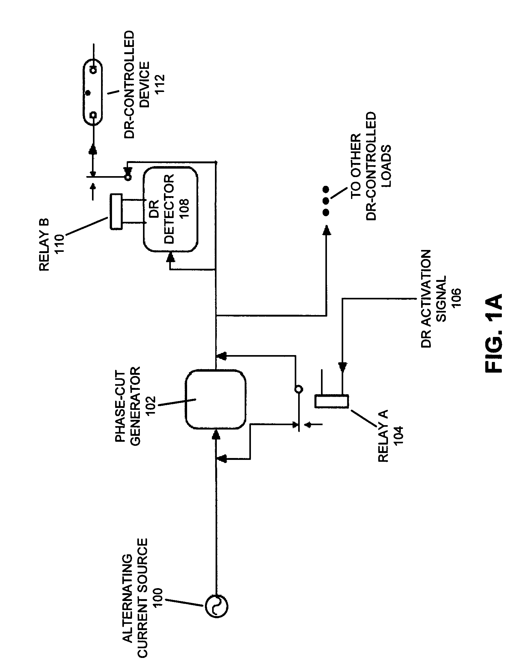
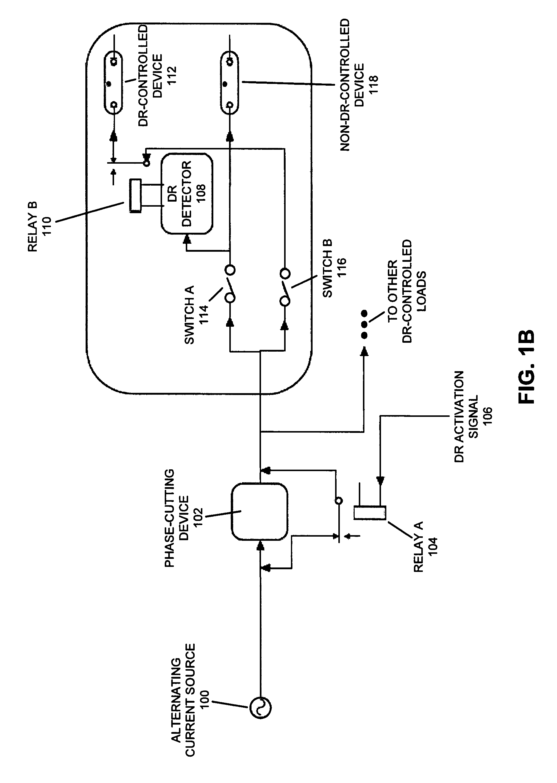
  • Method and apparatus for using power-line phase-cut signaling to change energy usage
  • Method and apparatus for using power-line phase-cut signaling to change energy usage
  • Method and apparatus for using power-line phase-cut signaling to change energy usage

Examples


Embodiment Construction

[0046]The following description is presented to enable any person skilled in the art to make and use the invention, and is provided in the context of a particular application and its requirements. Various modifications to the disclosed embodiments will be readily apparent to those skilled in the art, and the general principles defined herein may be applied to other embodiments and applications without departing from the spirit and scope of the present invention. Thus, the present invention is not limited to the embodiments shown, but is to be accorded the widest scope consistent with the claims.

Demand Response Requests

[0047]Providing sufficient energy generation capacity to handle peak demand intervals can involve considerable over-provisioning and expense. Utility companies and ISOs would prefer to avoid overload of the electrical grid by automatically shedding non-critical electrical loads during periods of peak usage. For instance, during periods of peak temperatures that cause a...


PUM


Abstract

One embodiment of the present invention provides a system that uses power-line phase-cut signaling to change energy usage for one or more devices that share a common power signal. During operation, the system receives a request to change power usage. In response to the request, the system inserts a phase-cut notch into the common power signal. A device that is located downstream from the inserted phase-cut notch detects this notch in the common power signal, and in response triggers a power-state change. For instance, the device may trigger a reduced-power state when it detects a phase-cut notch.

Description

RELATED APPLICATION[0001]This application claims priority under 35 U.S.C. section 119(e) to U.S. Provisional Application Ser. No. 60 / 808,830, entitled “Power Line Phase Cut Signaling,” by inventors Erik Page, Michael Siminovitch, Konstantinos Papamichael, Don Aumann, James Benya, and Joel Snook, filed on 25 May 2006, the contents of which are herein incorporated by reference.BACKGROUND[0002]1. Field of the Invention[0003]The present invention relates to a technique which facilitates changing energy usage in a given environment in response to an external request. More specifically, the present invention relates to a technique for using a power-line phase-cut signaling technique to change energy usage for one or more devices sharing a common power signal.[0004]2. Related Art[0005]The amount of energy which is used by a power grid can fluctuate greatly over time. This can be a problem, because there may not exist sufficient power-generation capacity to handle peak energy requirements. ...

Claims


Application Information

Patent Timeline
Patent Type & Authority Patents(United States)
IPC IPC(8): G05B11/01G05F1/00
CPCG06Q50/06H02M5/257H04B3/546H05B37/0263H04B2203/5412H05B47/185
Inventor BENYA, JAMES R.SNOOK, JOEL W.PAGE, ERIK R.SIMINOVITCH, MICHAELPAPAMICHAEL, KONSTANTINOSAUMANN, DON
Owner BENYA LIGHTING DESIGN
Learn More