Aircraft braking system

a technology of braking system and landing gear, which is applied in the field of aircraft, can solve the problem of second-to-last torque generation in the landing gear assembly, and achieve the effect of reducing the torsion load

Inactive Publication Date: 2013-02-19
AIRBUS OPERATIONS LTD
View PDF148 Cites 6 Cited by
  • Summary
  • Abstract
  • Description
  • Claims
  • Application Information

AI Technical Summary

Benefits of technology

[0005]The present invention seeks to provide a method of braked pivot turning an aircraft which generates lower torsion loads in the landing gear structure and / or mitigates at least some of the above-mentioned problems.
[0019]The aircraft may further comprise a nose wheel. It will be understood that turning the nose wheel at an angle to the centre line of the fuselage, may improve the turning circle of the aircraft and / or reduce stresses in the aircraft landing gear and particularly the nose landing gear. The aircraft may of course, comprise a plurality of nose wheels, and references to the nose wheel shall be interpreted accordingly. The method according to embodiments of the present invention may further include the step of turning the nose wheel at an angle to the centre-line of the aircraft fuselage. The angle is preferably greater than 30 degrees. More preferably the angle is greater than 45 degrees. More preferably the angle is greater than 60 degrees.
[0029]The method may include the step of receiving a signal relating to the application of brakes to the wheels of the aircraft landing gear (for example when the pilot applies the landing gear brakes) and applying the braking force according to the invention in dependence on this signal. Embodiments of the present invention may thereby provide a method which selectively controls the braking of wheels on an aircraft landing gear during an aircraft braked pivot turn, with a relatively low input from the aircraft pilot.
[0033]The brake control system may comprise a brake input receiver for receiving a signal relating to the application of brakes to the wheels of the aircraft landing gear, wherein the brake control system is arranged to effect the braking force in dependence on the signal received by the brake input receiver. The brake input receiver may receive the signal when the pilot applies the landing gear brakes. Embodiments of the present invention may thereby provide a brake control system which selectively controls the braking of wheels on an aircraft landing gear during an aircraft braked pivot turn, with a relatively low input from the aircraft pilot.
[0045]via the braking of at least one wheel, a greater braking force is applied to the outer side of the bogie of said landing gear assembly than to the inner side. It will be understood that the inner side of the bogie is located, when the aircraft is on the ground, closer to the fuselage than the outer side. It will also be understood that embodiments of such a method may be of particular advantage when the centre of turning is located outside the landing gear assembly.

Problems solved by technology

In addition however, it is thought that a secondary torque is generated in the landing gear assembly due to the differential braking force applied to either side of the bogie.

Method used


Image

  • Aircraft braking system
  • Aircraft braking system
  • Aircraft braking system

Examples


first embodiment

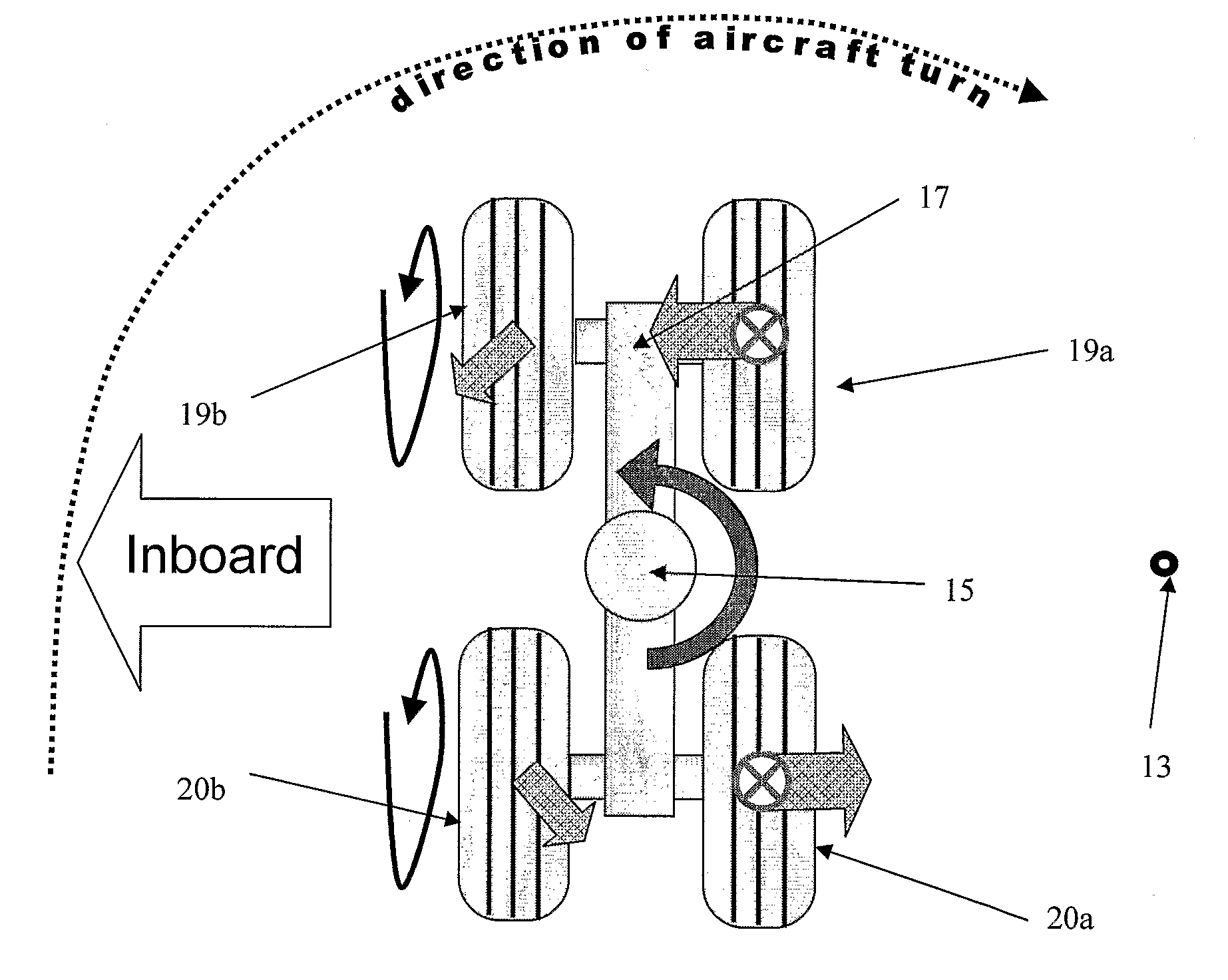
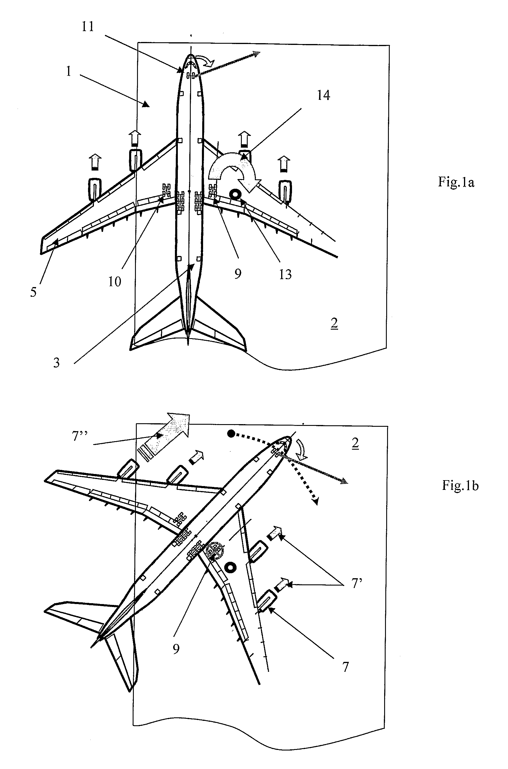
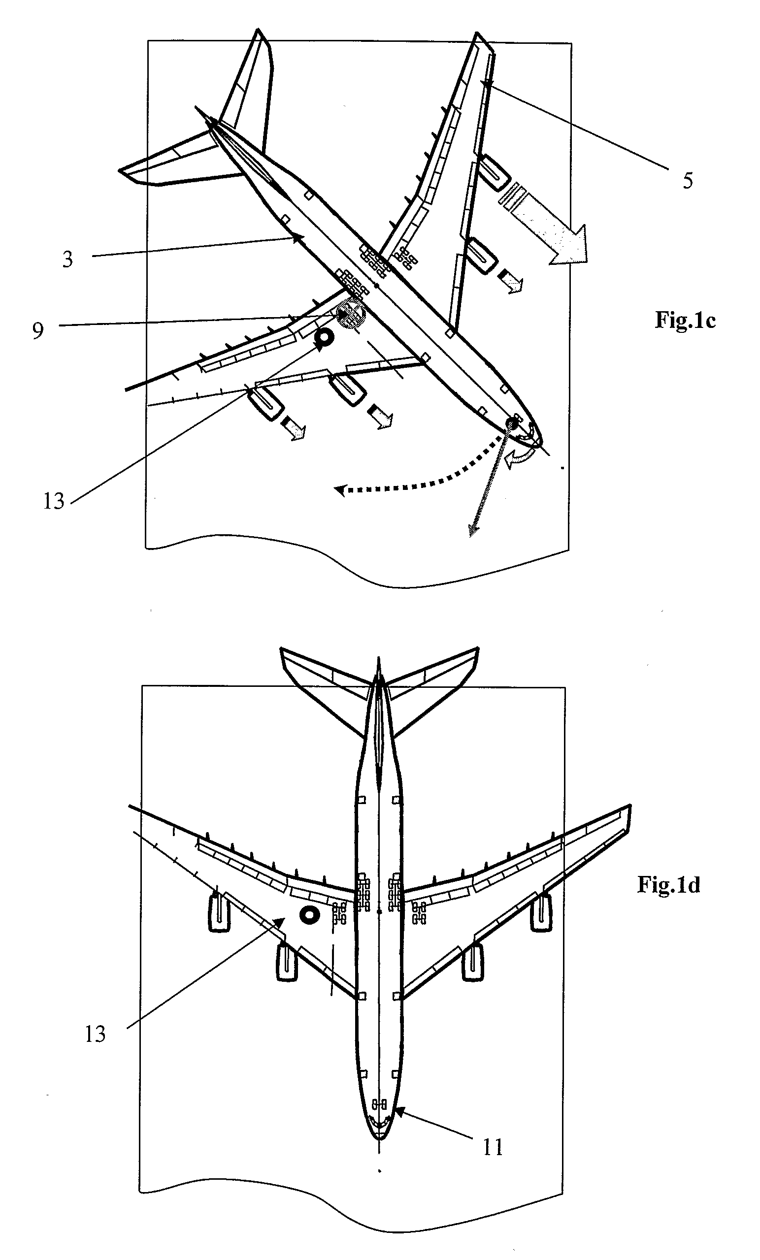
[0055]As is known in the art, to effect a first type of braked pivot turn the pilot performs three steps. First the nose wheel 11 is turned to one side. Then the pilot applies the brakes to the wheels of one of the landing gear 9 as indicated by the crossed-circle in FIGS. 1b and 1c. Finally a thrust is generated suitable for turning the aircraft. In the first embodiment the forward thrust 7″ of the left outermost engine is increased above idle. The net effect of the engine thrusts is a net thrust (not shown). The net thrust acts through a centre of thrust (not shown) spaced apart from the centre line of the fuselage, and close to the left-hand outermost engine.

[0056]The aircraft thus turns in a relatively small turning circle about a centre of turning 13 located close to the landing gear 9 on which brakes are applied. The landing gear travels, initially in a forward motion, in a tight circle 14 (the movement of the landing gear has been exaggerated for the sake of clarity). When th...

second embodiment

[0066]According to the invention (not shown) the aircraft is provided with a brake control system comprising a control unit, a ground speed receiver and a nose wheel angle receiver. The brake control system also comprises a brake input receiver which receives a signal when the pilot attempts to apply the brakes to the wheels of the landing gear.

[0067]The control unit is arranged to receive signals relating to the aircraft speed and the nose wheel angle via the ground speed receiver and a nose wheel angle receiver. The control unit is also arranged to compare the signal received from the ground speed receiver and the signal received from the nose wheel indicator, to parameter reference thresholds stored in a database within the brake control system. In the second embodiment, the aircraft speed is below the threshold value of 20 knots, and the nose wheel angle is greater than the threshold value of 60 degrees from the centre of the fuselage.

[0068]During use, the brake input receiver r...


PUM


Abstract

A method of braked pivot turning an aircraft, the aircraft comprising a fuselage and a landing gear assembly located to one side thereof. The landing gear comprises a bogie with wheels mounted thereon, at least one wheel being located on a first side of the bogie and at least one wheel being located on a second side of the bogie. The method includes the steps of applying thrust (7″) for moving or turning the aircraft, and via the braking of at least one wheel, applying a greater braking force to the first side of the bogie than to the second side. The first side is located closer to the center of turning of the aircraft than the second side. The method thereby generates relatively low torque loads in the landing gear leg, reducing fatigue damage. A brake control system is also provided for selectively braking wheels during a turn.

Description

RELATED APPLICATIONS[0001]The present application is based on International Application Number PCT / GB2006 / 004206 filed Nov. 10, 2006, and claims priority from British Application Number 0523069.3 filed Nov. 11, 2005, the disclosures of which are hereby incorporated by reference herein in their entirety.TECHNICAL FIELD[0002]The present invention relates to aircraft and in particular to a method of maneuvering an aircraft on the ground.BACKGROUND TO THE INVENTION[0003]It is desirable for aircraft, and particularly large aircraft, to be able to manoeuvre on the ground within a tight turning circle. To turn an aircraft in a tight turning circle it is known to typically perform a ‘braked pivot turn’. The braked pivot turn is typically effected by turning the aircraft nose wheel, applying differential engine thrust and applying the brakes to all the wheels of one of the landing gear, broadly speaking around which, the aircraft turns.[0004]Such a manoeuvre generates significant torsion loa...

Claims


Application Information

Patent Timeline
Patent Type & Authority Patents(United States)
IPC IPC(8): B64F1/02B60T8/00B64C25/48
CPCB64C25/48B60T8/00
Inventor THOMPSON, ROBERT IAN
Owner AIRBUS OPERATIONS LTD
Why Eureka
Try Eureka