Multiple wheel vehicle

a multi-wheel vehicle and wheel technology, applied in the direction of rider propulsion, cycle equipment, cycle stands, etc., can solve the problems of increasing cost and weight, affecting design, etc., to improve camber thrust, cornering property and steering stability, and maintain constant length of joint parts. , the effect of reliable and smooth interlocking

Active Publication Date: 2013-02-19
KANOU KINYA
View PDF16 Cites 5 Cited by
  • Summary
  • Abstract
  • Description
  • Claims
  • Application Information

AI Technical Summary

Benefits of technology

[0062]Since the vehicle according to the present invention comprises the above, when a one-side wheel is pushed up from a road surface, a one-side swinging arm and the tilted member tilt integrally around a first shaft centerline, and a one-side cord-like part is pulled in the direction of winding around a first circular surface. At this time, the change-direction member operates in a balance-like or pulley-like fashion and pulls the other-side cord-like part in the direction of rewinding from the first circular surface; therefore, it can push down the other-side wheel toward the road surface via the other-side tilted member and the swinging arm.
[0063]Consequently, the interlocking device can press down the other-side wheel in response to the pushing up of the one-side wheel with an equal force. Therefore, at the time of circling and turning about with inclining a vehicle body and at the time of running on a widthwise sloping road surface and the like, it enables to incline freely the two wheels together with the vehicle body while keeping a ground-contacting-pressure of the two wheels equal and to improve the camber thrust, cornering property, and steering stability.
[0064]The above-mentioned cord-like part extends in the z-axis direction perpendicular to the first and second shaft centers, and comprises a joint part extending along a tangential line of the first circular surface part and the second circular surface part. Therefore, in a tilting motion of the tilted member, the length of the joint part can be kept constant, a shifting of the cord-like part caused by the repetitive tilting motion can be prevented, and a reliable and smooth interlocking can be achieved.
[0065]In the interlocking device, when the tilted member is fixed on the swinging arm in enabling tilting integrally, the tilted member can be attached at a free phase angle (an angle around the first shaft center) with respect to the swinging arm. That is to say, the interlocking device can be provided in various positions and can highly enhance the possibility of designing of the multiple wheel vehicle.BRIEF EXPLANATION OF THE DRAWING
[0066][FIG. 1] A perspective view of a multiple wheel vehicle showing an example of the present invention (an example of the multiple wheel vehicle comprising two wheels on a rear wheel side).
[0068][FIG. 3] An enlarged perspective view of swinging arms with an interlocking device.

Problems solved by technology

However, this largely limits an arrangement of the movement-direction changing system, so that there is a problem that possibility of designing becomes impaired.
And, it is necessary to provide with the cushion spring in each of the swinging arms; therefore, there are also problems of increases in cost and weight.

Method used


Image

  • Multiple wheel vehicle
  • Multiple wheel vehicle
  • Multiple wheel vehicle

Examples


Embodiment Construction

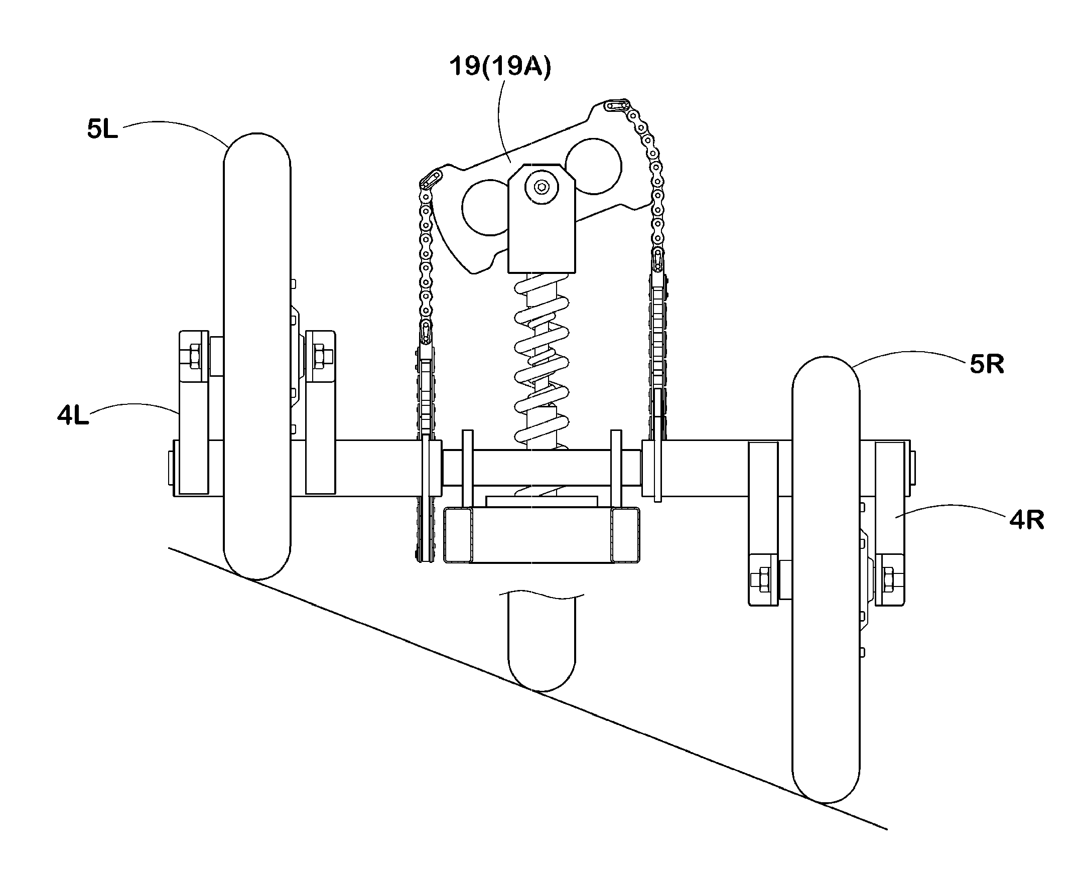
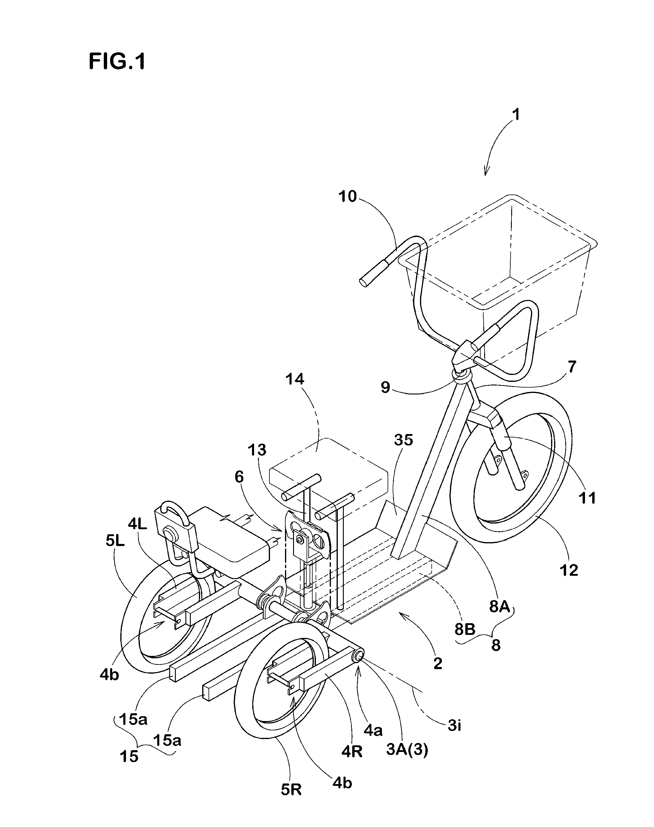
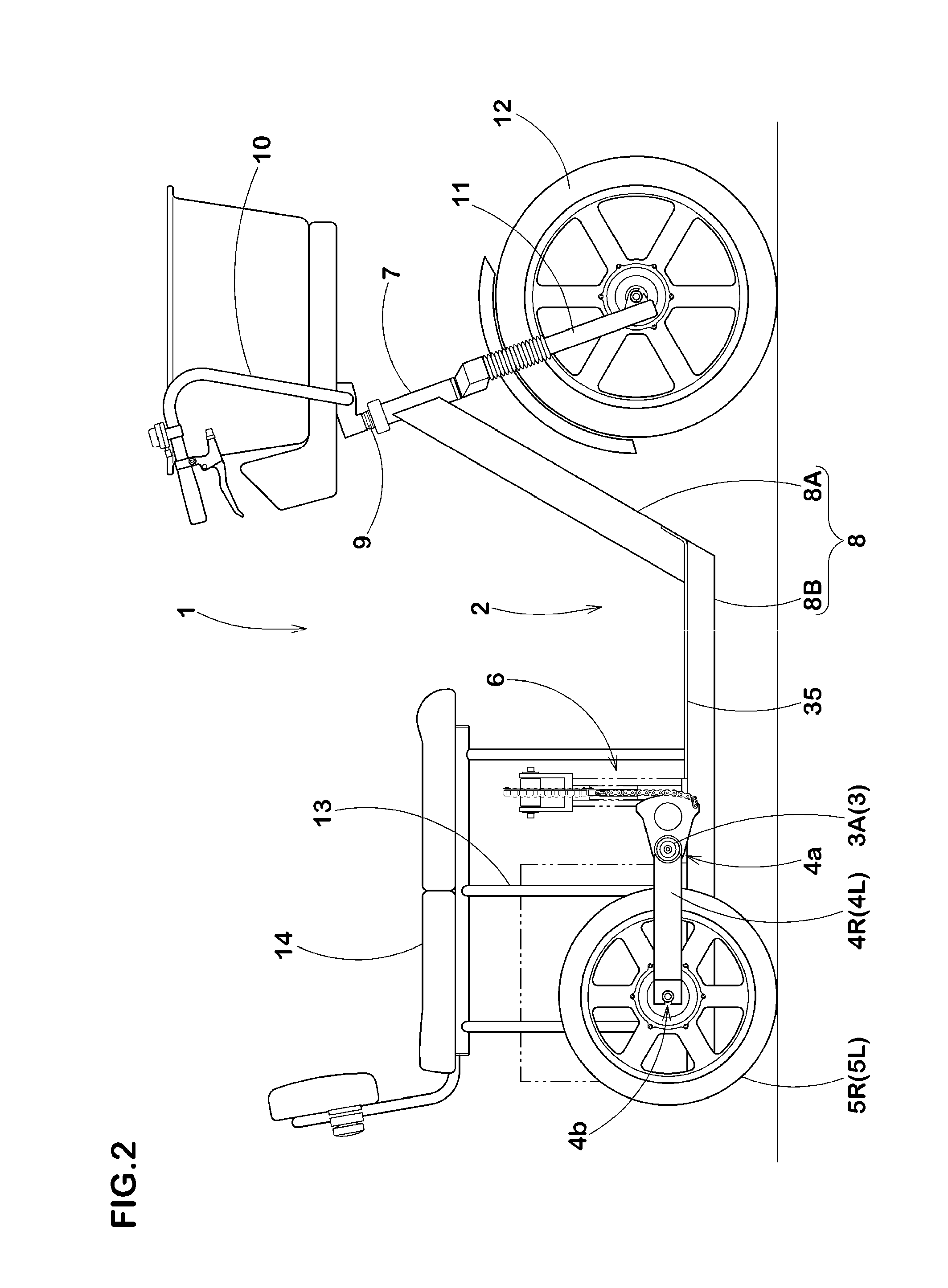
[0114]Hereinafter, embodiments of the present invention will be described in detail. As shown in FIG. 1, a multiple wheel vehicle 1 according to the present invention comprises:[0115]one-side and another-side swinging arms 4L and 4R, wherein each of swinging arms comprises[0116]one-side end portion 4a supported pivotably with each of right and left support shaft portions 3A supported with a frame 2 of the skeleton of the vehicle and extending on the same shaft center line 3i; [0117]wheels 5L and 5R mounted on the respective other-side end portions 4b of the one-side and other-side swinging arms 4L and 4R; and[0118]an interlocking device 6 for interlocking the one-side and other-side swinging arms 4L and 4R alternately up-and-down.

[0119]Incidentally, FIGS. 1 to 13 show a multiple wheel vehicle 1 having a two-rear-wheel type comprising two wheels on the rear wheel side (so-called a first embodiment). FIGS. 18 to 22 show a multiple wheel vehicle 1 having a two-front-wheel type comprisi...


PUM


Abstract

A multiple wheel vehicle according to the present invention enables to incline freely the two wheels together with the vehicle body while keeping the ground contacting pressures of the two wheels equal. The multiple wheel vehicle comprises a pair of swinging arms 4 each comprising one-side end portion supported pivotably with right and left support shaft portions 3A and an interlocking device 6 for interlocking them alternately up-and-down. The interlocking device 6 comprises a pair of tilted members 17, a divertible member 19, and a cord-like body 20 connecting them. Each of the tilted members 17 comprises a first circular surface part 21 that has a center of a circular arc as a shaft center 3i of the support shaft portion 3A, and tiltably supported integrally with the swinging arm 4. The above-mentioned divertible member 19 is provided on the right and left and on one-side and another-side with one-side and another-side second circular surface parts 26 which has a center of the circular arc as a second shaft center 18i which is in the direction perpendicular to each of the above-mentioned first shaft centers 3i, respectively. The above-mentioned cord-like body 20 comprises one-side cord-like part 20L connecting the first and second circular surface parts 21 on the one-side and other-side cord-like part 20R connecting the first and second circular surface parts 21 on the other-side.

Description

TECHNICAL FIELD[0001]The present invention relates to a multiple wheel vehicle comprising two wheels on a front wheel side and / or a rear wheel side, and the two-wheels are capable of inclining together with a vehicle body.BACKGROUND ART OF THE INVENTION[0002]As a three-wheels car comprising two wheels on a front wheel side, for example, a structure shown in FIG. 24 is known (see Patent Document 1, for example).[0003]This is provided in a front arm (a) with right and left swinging arms (c) and (c) of which one-side end portion is pivoted via a support shaft (b), and a wheel (d) mounded on another-side end portion of each of the swinging arms (c). And, to divide a load acting on a front part of the car between the right and left wheels (d) and (d), the car comprises a balance lever (h) pivotally supported via a holding shaft (g) on an upper part of the above-mentioned front arm (a), and a movement-direction changing system (e) comprising a cushion spring (i) and (i) positioned between...

Claims


Application Information

Patent Timeline
Patent Type & Authority Patents(United States)
IPC IPC(8): B62D9/02B60G21/05B62H1/12B62K5/02B62K5/05B62K5/06B62K5/08B62K25/12B62M1/24B62M1/28
CPCB62K5/025B62K5/027B62K5/05B62K5/10B62K2005/001
Inventor KANOU, KINYA
Owner KANOU KINYA
Why Eureka
Try Eureka