Thrust recovery, or other valve, containing two independently actuated doors and control system

a technology of a control system and a door actuator, applied in the direction of fuselage, weight reduction, aircraft accessories, etc., can solve the problems of high control resolution required during flight, the aerodynamic torque of the valve can be very great when, and the addition of system weight, complexity and cos

Active Publication Date: 2013-02-19
HONEYWELL INT INC
View PDF18 Cites 20 Cited by
  • Summary
  • Abstract
  • Description
  • Claims
  • Application Information

AI Technical Summary

Problems solved by technology

Aircraft which utilize conventional thrust recovery valves, or other skin mounted cabin air exhaust valves, face several challenges in their design and performance.
The first challenge is that there are times when a high resolution of control is required during flight at high differential pressures across the fuselage.
The second challenge is that the aerodynamic torque on the valve can be very great when the valve is opened because the frontal area of the valve is in the slipstream of air passing by the valve.
Another challenge is how to optimize ram air ingress of air from outside the airplane during negative pressure relief operation.
This ram air scoop adds system weight and complexity and cost.
An additional challenge is that thrust recovery valves are expensive and heavy, so having more than two thrust recovery valves can be wasteful.
But, in the event of a mechanical failure of the valve, having two or one thrust recovery valves can limit the ability to dispatch the airplane with one thrust recovery valve “blocked” closed, since air distribution and positive and negative pressure relief functions are compromised (higher probability that after the failure of the remaining valve a hazardous event could occur).

Method used


Image

  • Thrust recovery, or other valve, containing two independently actuated doors and control system
  • Thrust recovery, or other valve, containing two independently actuated doors and control system
  • Thrust recovery, or other valve, containing two independently actuated doors and control system

Examples


Embodiment Construction

[0025]The following detailed description is of the best currently contemplated modes of carrying out the invention. The description is not to be taken in a limiting sense, but is made merely for the purpose of illustrating the general principles of the invention, since the scope of the invention is best defined by the appended claims.

[0026]Various inventive features are described below that can each be used independently of one another or in combination with other features. However, any single inventive feature may not address any of the problems discussed above or may only address one of the problems discussed above. Further, one or more of the problems discussed above may not be fully addressed by any of the features described below.

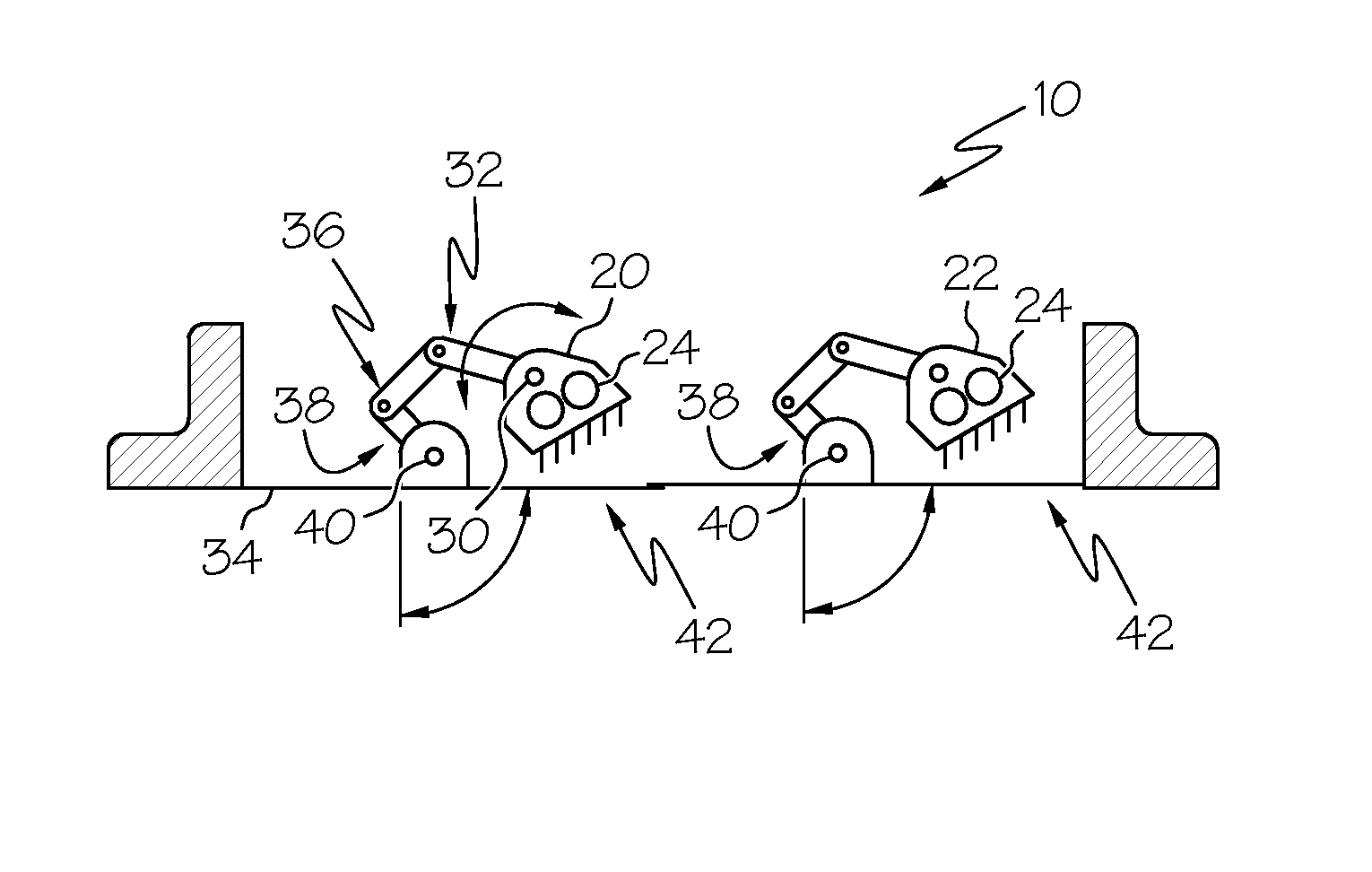
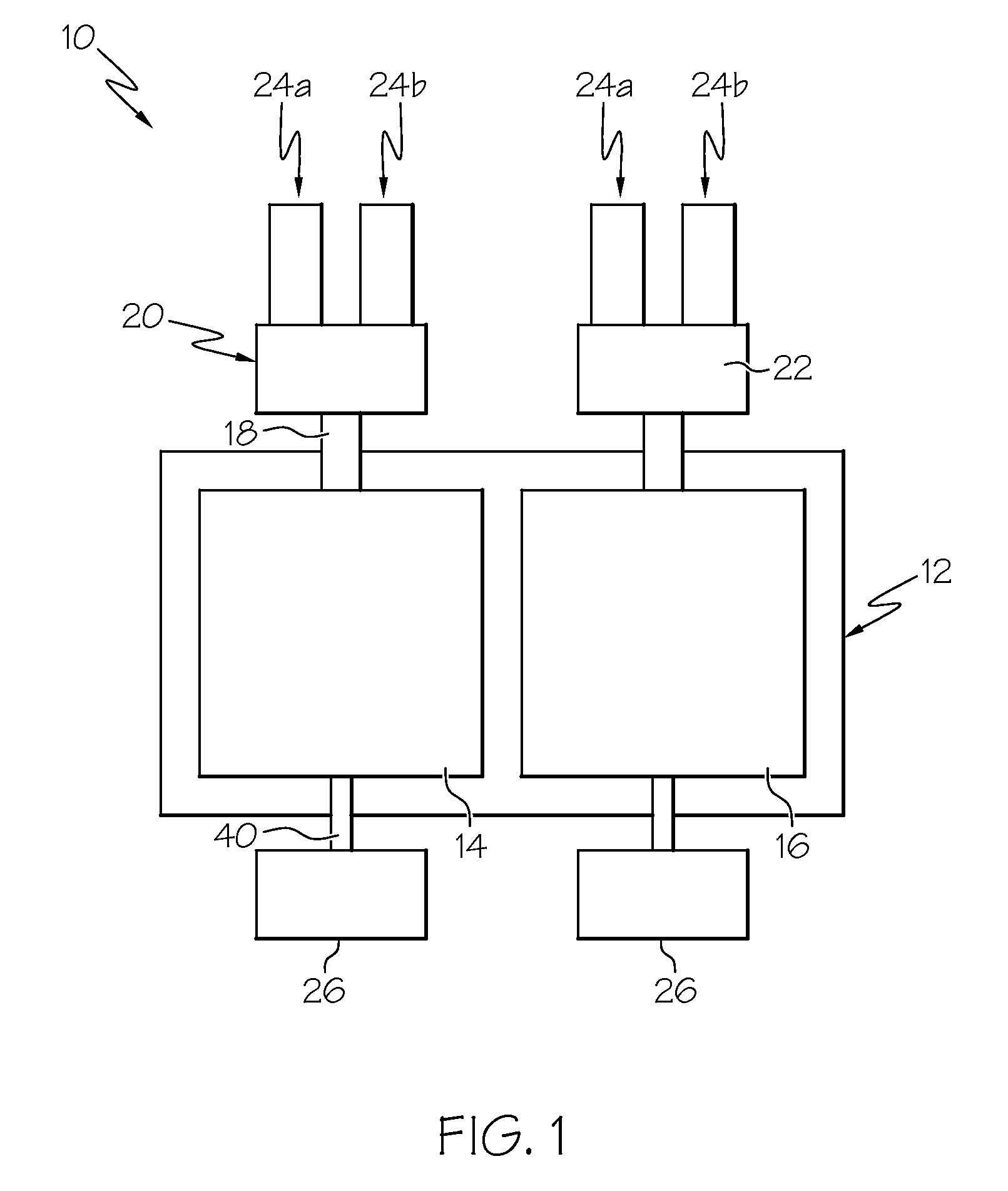
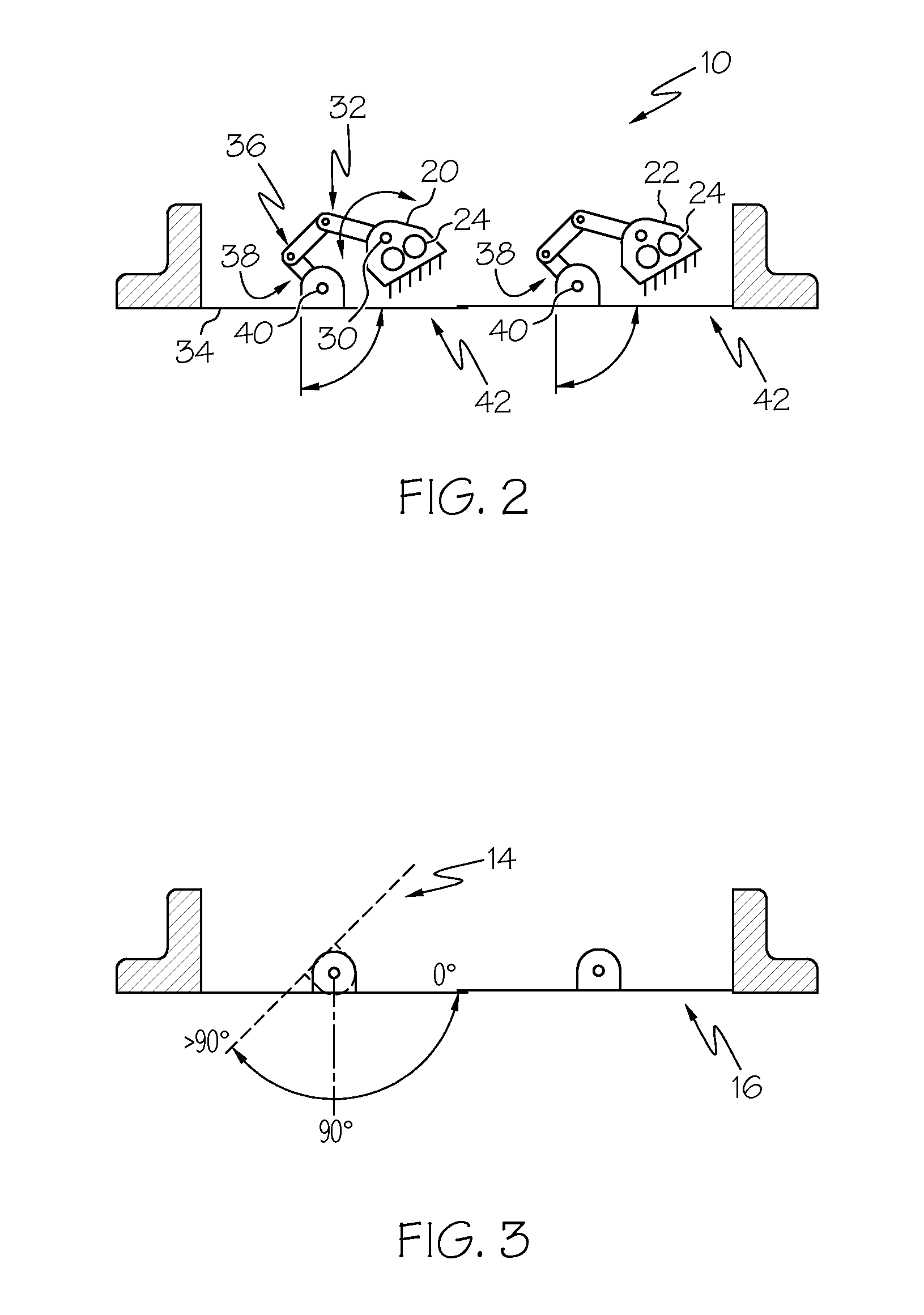
[0027]Broadly, embodiments of the present invention provides a thrust recovery valve that has two flaps, with each flap controlled independently via its own rotary actuator. Embodiments of the present invention also provide a cabin pressure control sys...


PUM


Abstract

A thrust recovery valve has two flaps, with each flap controlled independently via its own rotary actuator. Embodiments of the present invention also provide a cabin pressure control system that includes one or two thrust recovery valves and the controls architecture to efficiently operate the valves. On each thrust recovery valve, only one door can be operated during flight, making less effective area change per unit time (relative to the operating both doors at the same time), allowing higher resolution of valve control. Further, the valve doors can be made such that the primary door that is operated in flight is smaller than the other door (mostly only operated on the ground). Because the doors of the thrust recovery valve can be operated independently, the forward door of each valve can be rotated such that the door creates a ram air “scoop” to ingress air to prevent negative pressure from building up beyond a specified limit.

Description

BACKGROUND OF THE INVENTION[0001]The present invention relates to a thrust recovery valve and more particularly, to a thrust recovery valve having two flaps, with each flap controlled independently via its own actuator. The present invention further relates to a cabin pressure control system that includes one or two thrust recovery valves.[0002]Aircraft which utilize conventional thrust recovery valves, or other skin mounted cabin air exhaust valves, face several challenges in their design and performance.[0003]The first challenge is that there are times when a high resolution of control is required during flight at high differential pressures across the fuselage. The high resolution is required because the control of cabin pressure requires very small valve aperture changes for each periodic valve adjustment.[0004]The second challenge is that the aerodynamic torque on the valve can be very great when the valve is opened because the frontal area of the valve is in the slipstream of ...

Claims


Application Information

Patent Timeline
Patent Type & Authority Patents(United States)
IPC IPC(8): B64D13/02
CPCB64D13/02Y02T50/44Y02T50/40
Inventor HORNER, DARRELL
Owner HONEYWELL INT INC
Why Eureka
Try Eureka