Stent grafts for the thoracic aorta

a stent and aorta technology, applied in the field of medical devices, can solve the problems of difficulty for physicians to determine whether the fenestration or the scallop are correctly aligned, and achieve the effect of reducing the overall diameter of the stent graft and reducing the selected distan

Active Publication Date: 2013-02-19
COOK MEDICAL TECH LLC
View PDF12 Cites 9 Cited by
  • Summary
  • Abstract
  • Description
  • Claims
  • Application Information

AI Technical Summary

Benefits of technology

[0009]The stent graft can be mounted onto a deployment device such that at the proximal end of the stent graft the diameter reducing ties are at the inner side of what would be the curve of the deployment device to fit the curved lumen and at the distal end they are on the outer side of the curved lumen. This has a number of advantages. A first is that upon partial release the outer side of the curve at the proximal end expands more fully while at the same time still being maneuverable which allows the fenestration or scallops to be more opened and hence easier to visualise and position correctly. A second advantage is that when the diameter reducing ties are released by withdrawing the release wire there is a certain degree of friction between the release wire and the graft material through which it is stitched and pulling the release wire actually pulls the inner curve side of the proximal end of the stent graft towards the inner curve of the lumen thereby assisting the inner curve side of the proximal end of the stent graft to correctly engage with the wall of the lumen. A third advantage is that when the stent graft is in its curved and partially released configuration the release wire is substantially straighter between the ends of the graft thereby reducing the chance that the release wire will buckle and be difficult to withdraw when required.
[0019]whereby the selected distance is reduced thereby temporarily reducing the overall diameter of the stent graft.
[0024]whereby the selected distance is reduced thereby reducing the overall diameter of the stent graft.
[0033]whereby the selected distance is reduced thereby reducing the overall diameter of the stent graft.

Problems solved by technology

A stent graft is in a constricted form when it is delivered by endoluminal techniques to a deployment site within such a curved lumen and in that condition it is difficult for a physician to determine whether the fenestrations or scallop are correctly aligned to be positioned upon release by withdrawal of a covering sheath.
The problem with a curved lumen with significant continuing blood flow and such a staged release arrangement is that the proximal or leading edge of the stent graft particularly at the inner side of the curved lumen may not engage against the wall of the lumen and may fold in thereby blocking the desired flow path and allowing bypass to continue into the aneurysm.

Method used


Image

  • Stent grafts for the thoracic aorta
  • Stent grafts for the thoracic aorta
  • Stent grafts for the thoracic aorta

Examples


Embodiment Construction

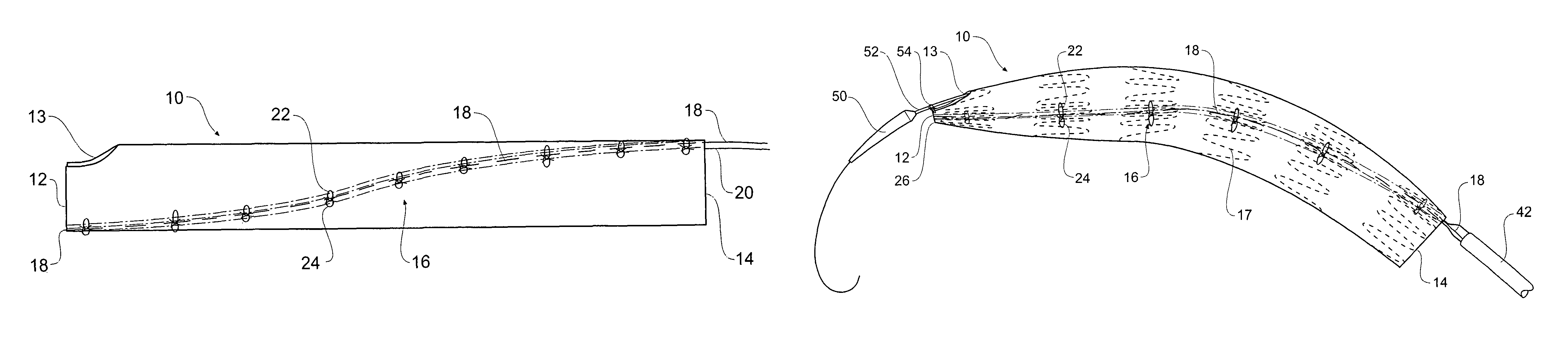
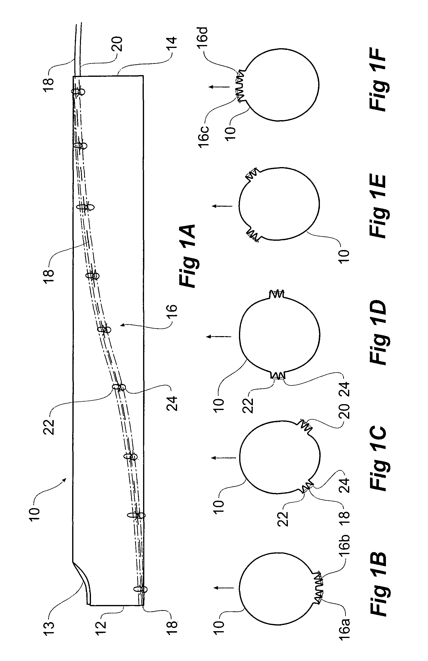
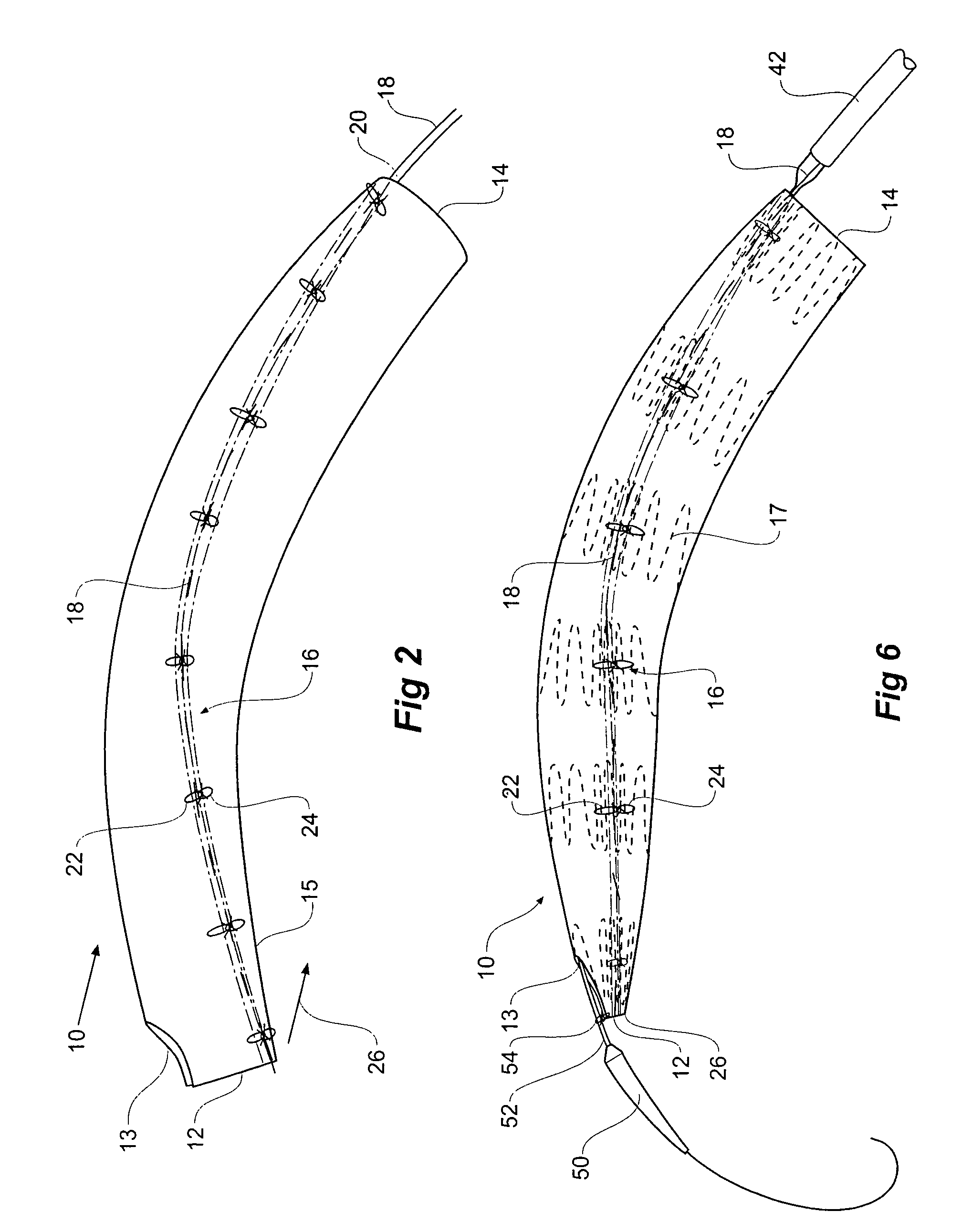
[0044]Now looking more closely at the drawings and in particular FIGS. 1A to F and FIG. 2 it will be seen that a stent graft 10 is a tubular body of a suitable graft material and has a proximal end 12 and a distal end 14. A scallop 13 is provided in the stent graft at the proximal end 12. The scallop would allow the stent graft to be deployed further around the thoracic arch of a patient thereby providing a larger landing zone for the stent graft without occluding the left subclavian artery. Stents on the stent graft are omitted in FIGS. 1 and 2 for the sake of clarity.

[0045]The stent graft is schematically depicted in a diameter reduced state by the use of a diameter reducing arrangement generally shown as 16. The diameter reducing arrangement includes release wires 18 and 20 which extend down each side of the stent graft in a part helical manner in opposite directions from the distal end 14 to the proximal end 12. The release wire 18 is stitched in and out of the graft material al...


PUM


Abstract

A method of temporarily reducing the diameter of a stent graft (10) and a stent graft with its diameter reduced. The stent graft has a tubular body and self expanding stents. The method comprising extending a release wire (18, 20) part helically along the graft material tube from substantially one side of the graft material tube at one end (14) of the graft material tube to substantially the opposite side of the graft material tube at the other end (12) of the graft material tube along the stent graft and stitching the release wire into the graft material tube, at each of a number of positions along the release wire looping flexible threads (22, 24) around the release wire and extending the flexible threads laterally around the circumference of the stent graft in each direction to a position away from the release wire, engaging the first flexible threads into the graft material or around struts of the stent, and drawing the ends of the thread together and tying ends of the thread to thereby temporarily reduce the overall diameter of the stent graft.

Description

CROSS-REFERENCE TO RELATED APPLICATIONS[0001]This application claims priority of provisional application Ser. No. 60 / 928,731, filed May 11, 2007.TECHNICAL FIELD[0002]This invention relates to a medical device and more particularly to a stent graft for mounting onto a deployment device for endovascular introduction.BACKGROUND OF THE INVENTION[0003]This invention will be particularly discussed in relation to stent grafts for placement into the thoracoabdominal aorta for the treatment of aneurysms and more specifically in relation to placement in a curved portion of the aorta such as the thoracic arch. The invention, however, is not so restricted and may be applied to stent grafts for placement in any lumen of the human or animal body.[0004]A stent graft particularly for the thoracic arch may have one or more fenestrations or a scallop at the proximal end to prevent occlusion of one or more of the major arteries which extend from the thoracic arch. A stent graft is in a constricted for...

Claims


Application Information

Patent Timeline
Patent Type & Authority Patents(United States)
IPC IPC(8): A61F2/06
CPCA61F2/07A61F2/954A61F2/962A61F2/95A61F2002/061A61F2250/001A61F2/89A61F2002/075A61F2220/0075A61F2002/9511
Inventor HARTLEY, DAVID ERNESTDUCKE, WERNER DIETER
Owner COOK MEDICAL TECH LLC
Why Eureka
Try Eureka