Acoustic enhancement for photo detecting devices

a technology of photo detecting and acoustic enhancement, which is applied in the direction of optical radiation measurement, generator/motor, instruments, etc., can solve the problems of reducing the ability to detect very low signals, low quality, and little means to improve sensitivity after fabrication, so as to enhance the sensitivity of the photo detecting devi

Inactive Publication Date: 2013-02-19
UNIV OF TENNESSEE RES FOUND +1
View PDF7 Cites 1 Cited by
  • Summary
  • Abstract
  • Description
  • Claims
  • Application Information

AI Technical Summary

Benefits of technology

[0010]An electro-mechanical acoustic resonator is electronically coupled to a photo detecting device and an electronic signal with improved signal to noise ratio results. The photo detecting device produces a first electronic signal in response to a received light pulse, and the first electronic signal is received by the electro-mechanical acoustic resonator. The electro-mechanical acoustic resonator damps the electronic signal so that it has a signal to noise ratio (SNR) that is greater than the signal to noise ratio (SNR) of the first electronic signal.

Problems solved by technology

Photo detection device sensitivity to light pulses is generally developed during device fabrication, and there exists little means to improve sensitivity after fabrication.
However, these instruments have low quality factors that reduce their ability to detect very low signals.

Method used


Image

  • Acoustic enhancement for photo detecting devices
  • Acoustic enhancement for photo detecting devices
  • Acoustic enhancement for photo detecting devices

Examples


Embodiment Construction

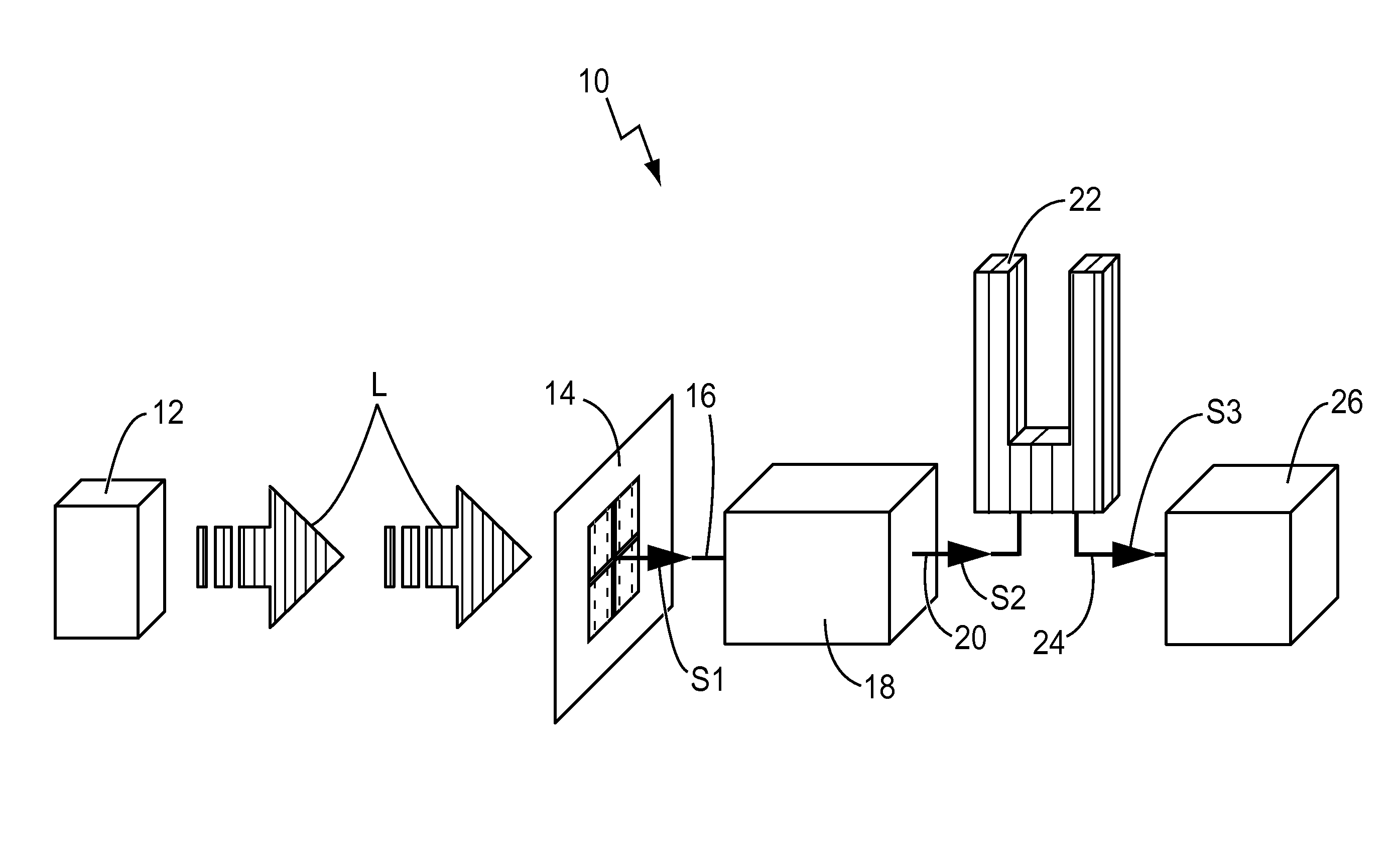
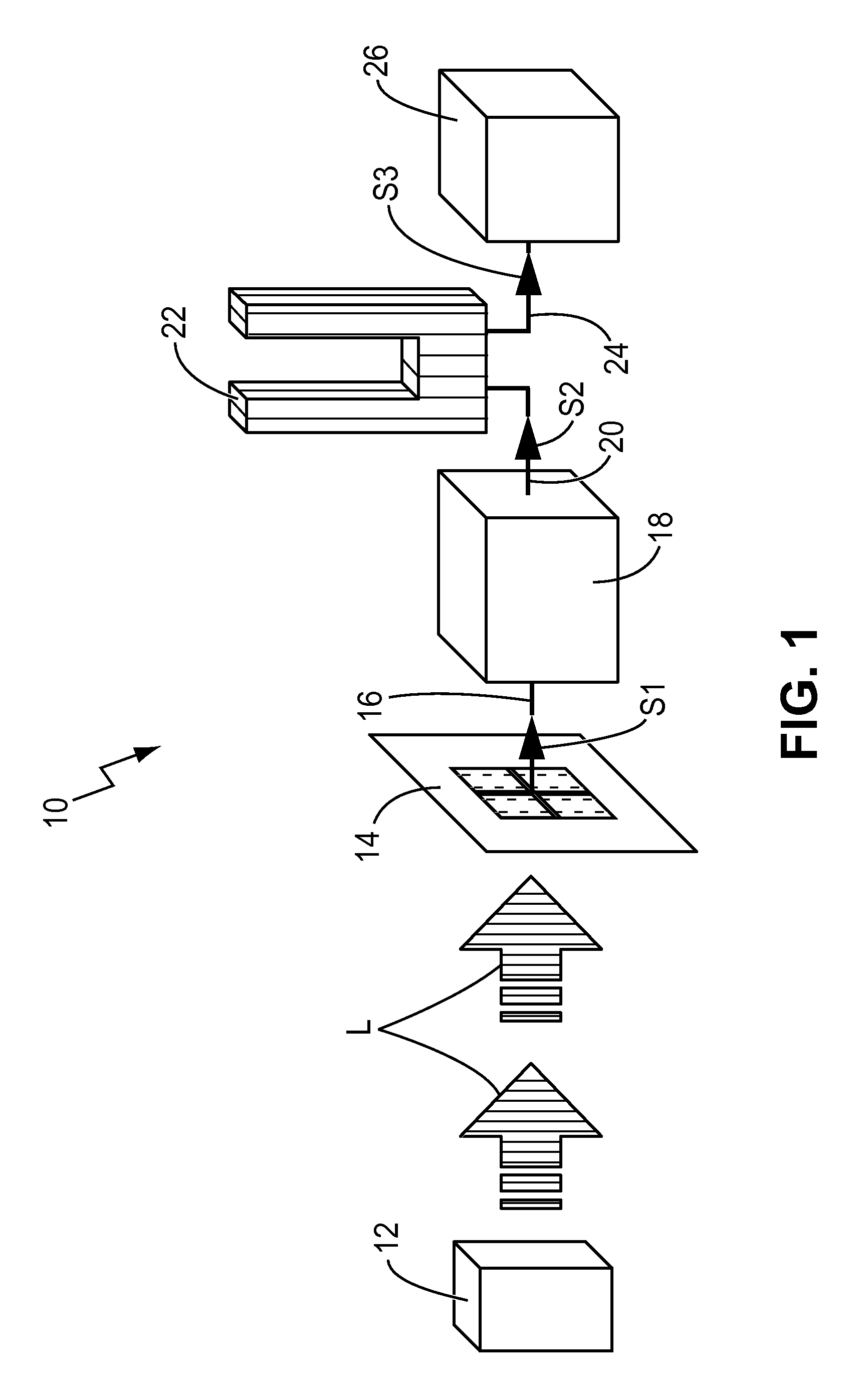
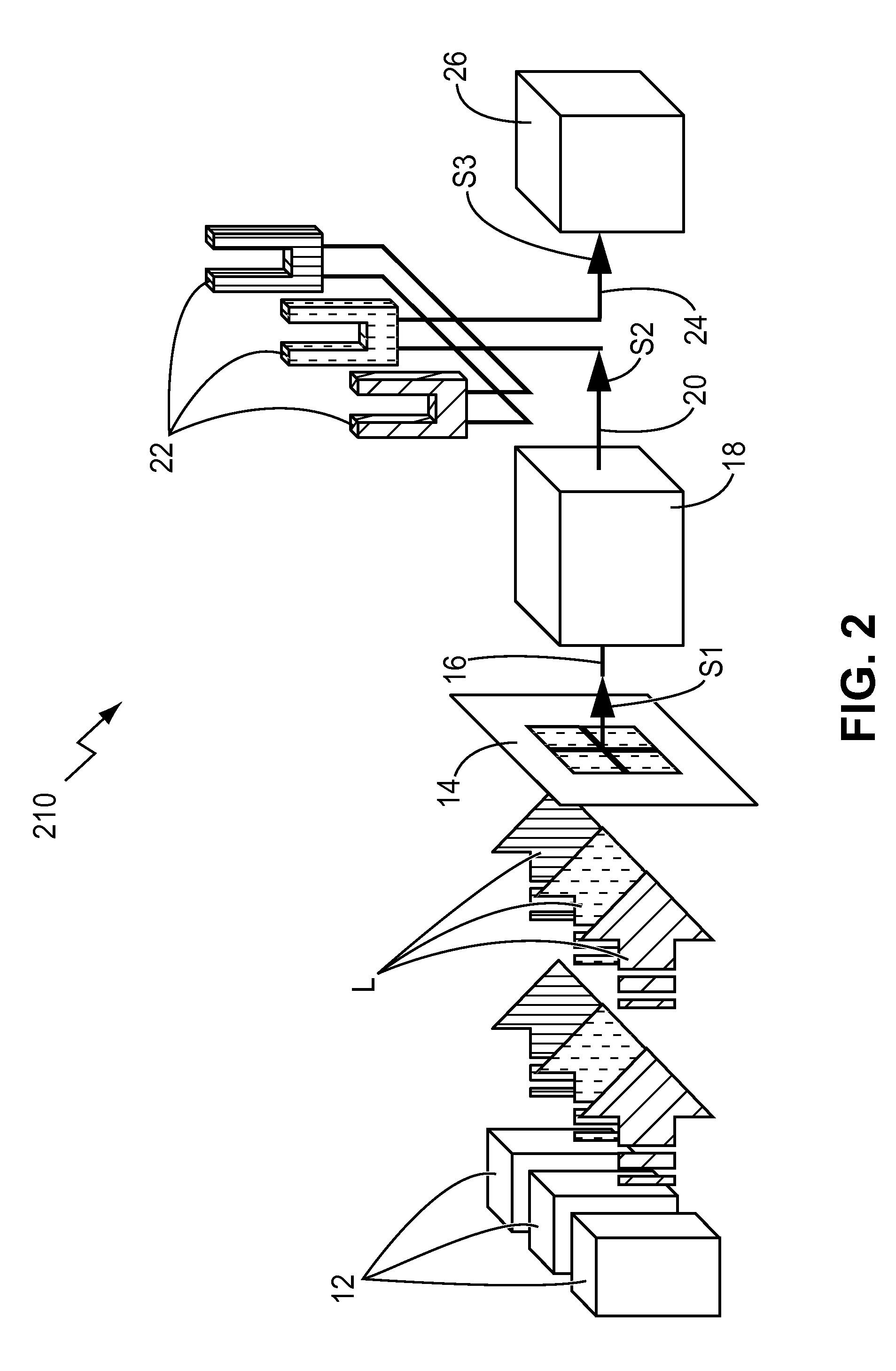
[0018]With reference first to FIG. 1, a first example of an enhanced sensitivity photo detecting device 10 is illustrated. A light source 12, such as a laser or a light emitting diode (LED) for example, emits a light pulse (L) through space as an electromagnetic wave of one or more photons. The wavelength of the light pulse (L) may be in the visible or invisible electromagnetic spectrum.

[0019]The light pulse (L) is received and sensed by a photo detecting device 14 such as a photoresistor, a photovoltaic, or a photodiode for example. It is important to choose a photo detecting device 14 with a sufficient response time to capture the speed and intensity of the light pulse (L) to be detected.

[0020]The output from the photo detecting device 14 is a voltage or current signal that increases with the increased intensity of the received electromagnetic radiation of the light pulse (L). It is this voltage or current that may be measured, filtered and / or stored for later use. To that end, a ...


PUM


Abstract

Provided are improvements to photo detecting devices and methods for enhancing the sensitivity of photo detecting devices. A photo detecting device generates an electronic signal in response to a received light pulse. An electro-mechanical acoustic resonator, electrically coupled to the photo detecting device, damps the electronic signal and increases the signal noise ratio (SNR) of the electronic signal. Increased photo detector standoff distances and sensitivities will result.

Description

STATEMENT REGARDING FEDERALLY SPONSORED RESEARCH AND DEVELOPMENT[0001]This invention was made with government support under Contract No. DE-AC05-00OR22725 awarded by the U.S. Department of Energy. The government has certain rights in the invention.BACKGROUND OF THE INVENTION[0002]1. Field of the Invention[0003]The present disclosure relates to photo detecting devices, and more specifically to improvements for providing enhanced sensitivity to photo detecting devices and methods of enhancing the sensitivity of photo detecting devices.[0004]2. Description of the Related Art[0005]Photo detecting devices are found in everything from television remote controls to advanced weapon guidance systems. Photo detecting devices are generally defined as any radiant electromagnetic detecting apparatus. Examples may include photoresistors, photovoltaics, photodiodes, etc.[0006]Electromagnetic radiation is classified by wavelength into radio, microwave, infrared, ultraviolet, X-rays and gamma rays. ...

Claims


Application Information

Patent Timeline
Patent Type & Authority Patents(United States)
IPC IPC(8): H01J40/14
CPCG01J1/44H01L31/02019H01L41/1132H10N30/302
Inventor THUNDAT, THOMAS G.SENESAC, LAWRENCE R.VAN NESTE, CHARLES W.
Owner UNIV OF TENNESSEE RES FOUND
Why Eureka
Try Eureka