Apparatus and method for charging an electric vehicle

a charging device and electric vehicle technology, applied in hybrid vehicles, secondary cell servicing/maintenance, capacitor propulsion, etc., can solve the problems that the charging device used to charge a low-voltage battery cannot be used to charge an ultracapacitor, and the reliability of the overall system may be compromised

Active Publication Date: 2013-02-19
GENERAL ELECTRIC CO
View PDF13 Cites 90 Cited by
  • Summary
  • Abstract
  • Description
  • Claims
  • Application Information

AI Technical Summary

Problems solved by technology

This can lead to multiple components and charging systems because the storage devices typically cannot be charged using charging systems for other storage devices.
In other words, a charging device used to charge a low-voltage battery typically cannot be used to charge an ultracapacitor or a high-voltage battery.
Because each charger type accordingly includes a system of electrical components, reliability of the overall system may be compromised because of the large number of components that may be used in order to provide this functionality.

Method used


Image

  • Apparatus and method for charging an electric vehicle
  • Apparatus and method for charging an electric vehicle
  • Apparatus and method for charging an electric vehicle

Examples


case 1

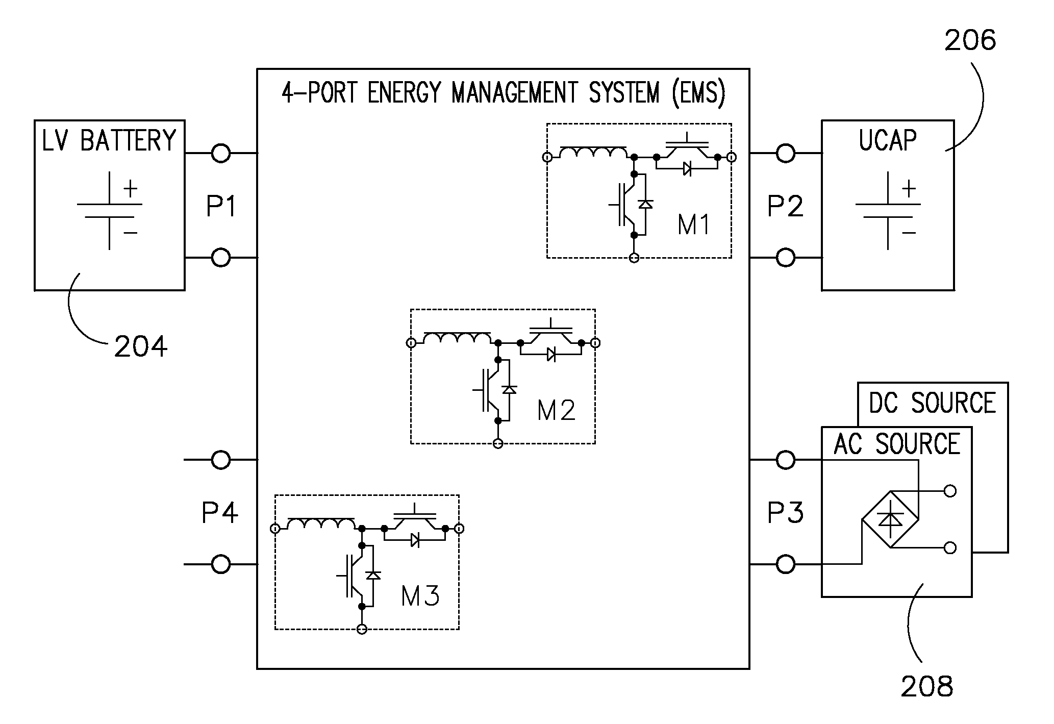
[0078] Input voltage at port 3476 is higher than battery voltage at port 1472. In this case module 2478 operates in buck mode and the current IL4480 in LU is regulated. Contactors KU 482 and KV 484 are closed, while M 486, KW 488 and UPOS 490 are open.

case 2

[0079] Input voltage at port 3476 is lower than battery voltage at port 1472. In this case contactors KU 482, M 486 and UPOS 490 are closed, while KV 484 and KW 488 are open. Module 2478 is inactive (M2U is permanently on), module 1492 operates in boost mode to boost the low input voltage up to some higher level. Module 3494 bucks this voltage back to the set voltage of the energy battery at port 1472. The current IL2496 in LW is controlled in a closed loop fashion.

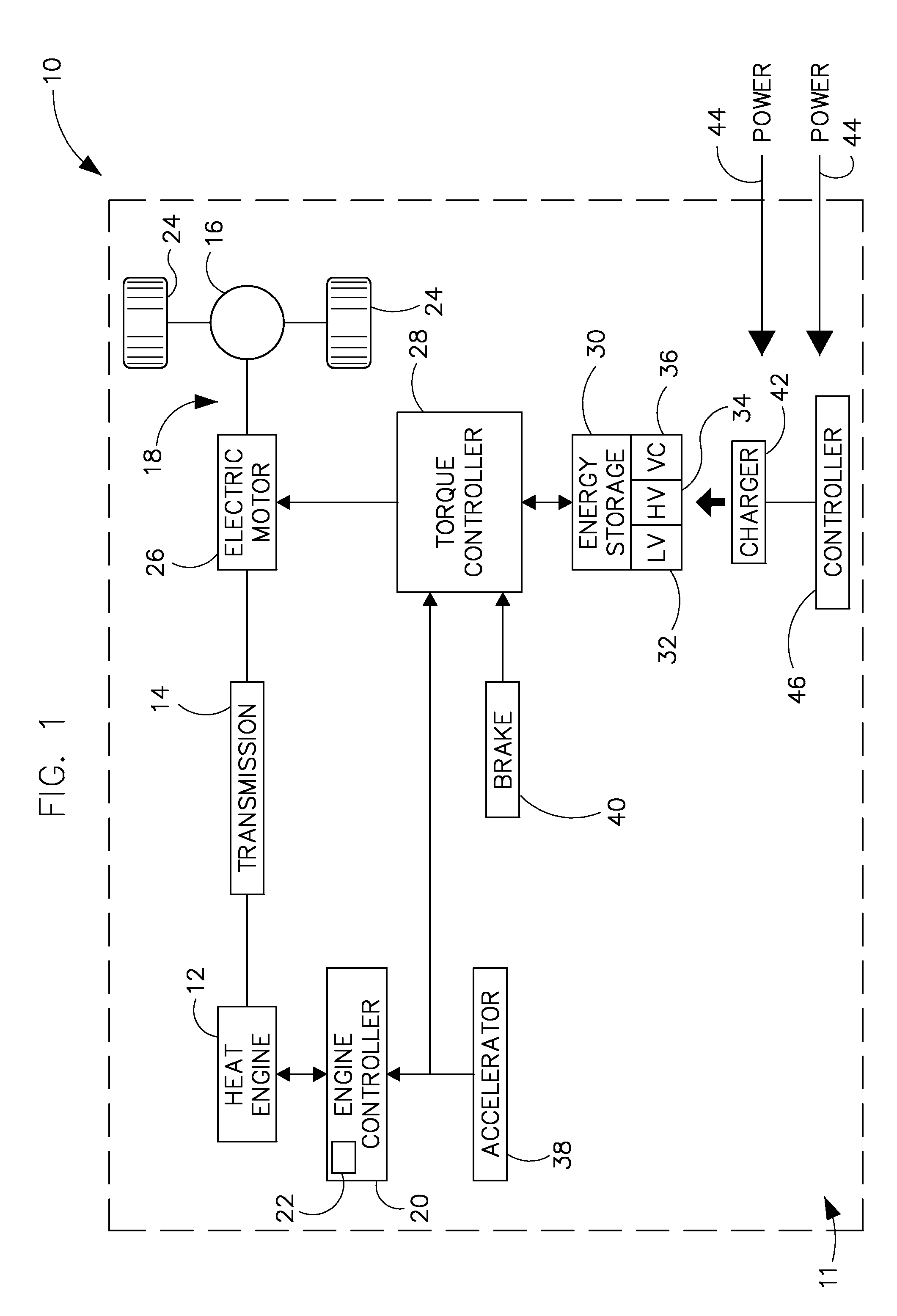
[0080]In todays commercially available EV and PHEV vehicles, energy and e-motor drivetrains typically include components from different vendors. As a result many units are duplicated, with many single point failure possibilities in the system. Thus, the integration of functions into one instead of three or four management units will result in a reliability improvement, according to embodiments of the invention. From the perspective of a battery manufacturer for example, where good knowledge of the battery cell behavior is...


PUM

PropertyMeasurementUnit
poweraaaaaaaaaa
DC energyaaaaaaaaaa
DC voltageaaaaaaaaaa

Abstract

An energy management system (ESMS) includes energy storage devices coupled to a vehicle drivetrain and configured to store DC energy, a power electronic conversion system having energy ports, the power electronic conversion system comprising a DC electrical converters, each DC electrical converter configured to step up and to step down a DC voltage, wherein each of the energy ports is coupleable to each of the energy storage devices and each of the energy ports is coupleable to an electrical charging system. The EV includes a controller configured to determine a voltage of each energy port having either an energy storage device or a DC electrical charging system coupled thereto, and electrically connect a first energy port to a second energy port such that at least one of the DC electrical converters either steps up or steps down an input DC voltage based on the determined voltage of each energy port.

Description

BACKGROUND OF THE INVENTION[0001]Embodiments of the invention relate generally to electric drive systems including hybrid and electric vehicles and, more particularly, to charging an electric vehicle using a multiport energy management system.[0002]Hybrid electric vehicles may combine an internal combustion engine and an electric motor powered by an energy storage device, such as a traction battery, to propel the vehicle. Such a combination may increase overall fuel efficiency by enabling the combustion engine and the electric motor to each operate in respective ranges of increased efficiency. Electric motors, for example, may be efficient at accelerating from a standing start, while internal combustion engines (ICEs) may be efficient during sustained periods of constant engine operation, such as in highway driving. Having an electric motor to boost initial acceleration allows combustion engines in hybrid vehicles to be smaller and more fuel efficient.[0003]Purely electric vehicles ...

Claims


Application Information

Patent Timeline
Patent Type & Authority Patents(United States)
IPC IPC(8): H01M10/44H01M10/46B60L50/16
CPCB60L11/005B60L11/1812B60L11/1862B60L11/1868B60L11/14Y02T10/70B60L2210/12B60L2210/14B60L2210/30B60L2210/40B60L2240/441B60L2240/445B60L2270/20Y02T10/7005Y02T10/7022Y02T10/7044Y02T10/7066Y02T10/7077Y02T10/7225Y02T10/7233Y02T10/7241Y02T90/127Y02T90/14B60L53/22B60L50/16B60L58/20B60L50/40B60L58/13Y02T10/7072Y02T10/62Y02T10/72Y02T90/12
Inventor KUSCH, RUEDIGER SOERENKING, ROBERT DEANSTEIGERWALD, ROBERT LOUIS
Owner GENERAL ELECTRIC CO
Why Eureka
Try Eureka