Sliding door assembly

a door and sliding technology, applied in the direction of door/window fittings, rain/draught deflectors, constructions, etc., can solve the problems of sliding windows, dissimilar items, and the joint of two or more items made of dissimilar materials, and achieve the effect of simple design and construction, high level of reliability, and high level of moisture barrier reliability

Active Publication Date: 2013-02-26
TIMOTHY J MCDONALD TECH
View PDF15 Cites 19 Cited by
  • Summary
  • Abstract
  • Description
  • Claims
  • Application Information

AI Technical Summary

Benefits of technology

[0012]The sliding door assembly of the present invention provides a door assembly provides a moisture barrier that has a high level of reliability while using a small lower threshold that is relatively comfortable for a user to traverse and that complies with the Americans with Disabilities Act. The present sliding door assembly maintains its high level of moisture barrier reliability even after the door becomes loose through normal wear and tear and the passage of time. The sliding door assembly continues to be of relatively simple design and construction using standard manufacturing techniques and is relatively easy to use and maintain.
[0013]The sliding door assembly of the present invention is comprised of a frame that has a header and a threshold joined by a first mullion with a first angled face and a second mullion with a second angled face. The header has at least one channel, each channel with a curved section and a straight section. A compression gasket is attached to the header, the threshold, the first mullion, and the second mullion. A sash, has a first jamb with a third angled face and a second jamb with a fourth angled face, the first jamb and the second jamb being joined by a top leg and a bottom leg. A post is pivotally attached to the top of the sash and protrudes through the channel and has a roller rotatably attached to its end. A keeper is located on the first mullion while a latch is attached to the first side jamb of the sash. The sash is slidable between an open position and a closed position such that when the sash is in the closed position, the latch is received within the keeper and presses the sash into pressing engagement with the gasket in order to create a seal between the sash and the frame. When the sash is in the closed position, the post is within the curved section of the channel. When the sash slides to the open position, the post travels from the curved section to the straight section. The first angled face faces the third angled face and the second angled face faces the fourth angled face whenever the sash is in the closed position. The header slopes downwardly in proceeding from the straight section of the channel to the curved section of the channel in order to gravitationally assist the sash in sliding toward the closed position. The threshold has an upwardly extending lip opposite the gasket in order to guide the sash between the closed position and the open position and prevent the bottom of the sash from popping out of the frame structure. The gasket is located within a channel that extends along a portion of the header, the threshold, the first mullion, and the second mullion. The threshold is laterally and downwardly sloped (from inner facing surface wall to outward facing surface wall) and has a weep hole at a lower end, the weep hole having a one-way valve therein. The one-way valve, which is a specially designed valve that may be similar to a medical valve, may but need not necessarily be spring-loaded.

Problems solved by technology

One problem in any envelope design is the junction between two or more items made from dissimilar materials such as where doors and windows integrate with the main building facade.
Operable windows are another problem area in building moisture intrusion.
Sliding windows present another problem in dealing with moisture penetration.
While it is possible to have storms that have winds that drive rain upwardly, the vertical vector component of such winds are not very large, therefore, the rain acts on the gasket with only a relatively small force, which the gasket is designed to handle.
The sides of the window wherein the sash rides in a track pose a different problem.
As the sash must travel up and down along this track, an airtight seal between sash and frame along the track is not possible.
However, the tolerances between the sash and the frame are very tight so that most if not all moisture is stopped at the junction of sash and frame.
The problems associated with moisture barrier protection for horizontal sliding sashes and more particularly sliding glass doors is much more challenging.
Therefore, the gasket that seals the junction between the two sashes is subject to rain any time the wind blows from the appropriate direction during a storm and as the door is at ground level, the lower part of the junction is subject to a rain load almost every shower due to the rain hitting the ground proximate the sash and splashing against the seal.
Additionally, the flanging systems used on the windows to deflect moisture that passes the sash-frame contact area cannot be effectively used on the lower part of the door.
Therefore, vertically disposed flanging systems that are commonly found on hung windows, which systems tend to be relatively wide, cannot be effectively deployed on a sliding glass door that has threshold height restrictions and that also requires that the threshold be subject to the load forces associated with people walking thereon.
Accordingly, moisture barrier systems found on sliding doors tend to be less reliable relative to other door and window moisture barrier systems.
Such a multiple flange configuration, even though it is relatively low in height, is somewhat uncomfortable to walk across and is difficult to bypass in a wheelchair that must pass across the several flanges.
Additionally, sliding doors tend to be larger relative to most windows, therefore, they tend to become “loose” over time through repeated use.
As such doors require tight interfitting parts in order to achieve a strong moisture barrier capability, such loosening tends to degrade the moisture barrier capabilities of the door.

Method used


Image

  • Sliding door assembly
  • Sliding door assembly
  • Sliding door assembly

Examples


Embodiment Construction

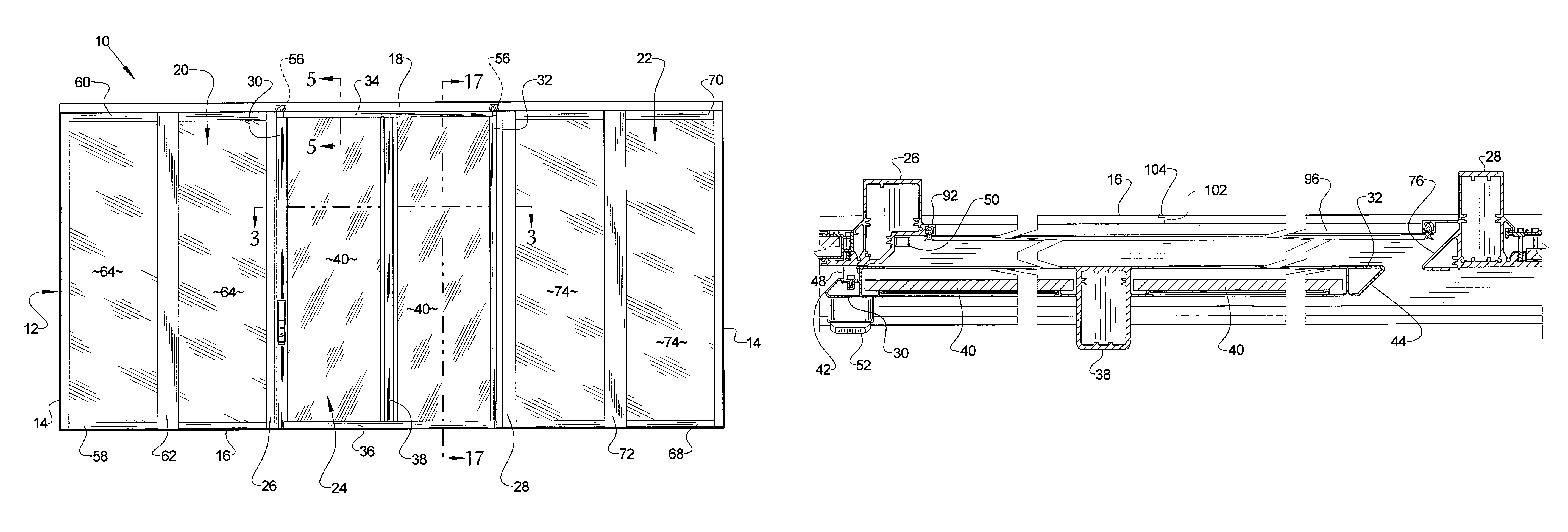
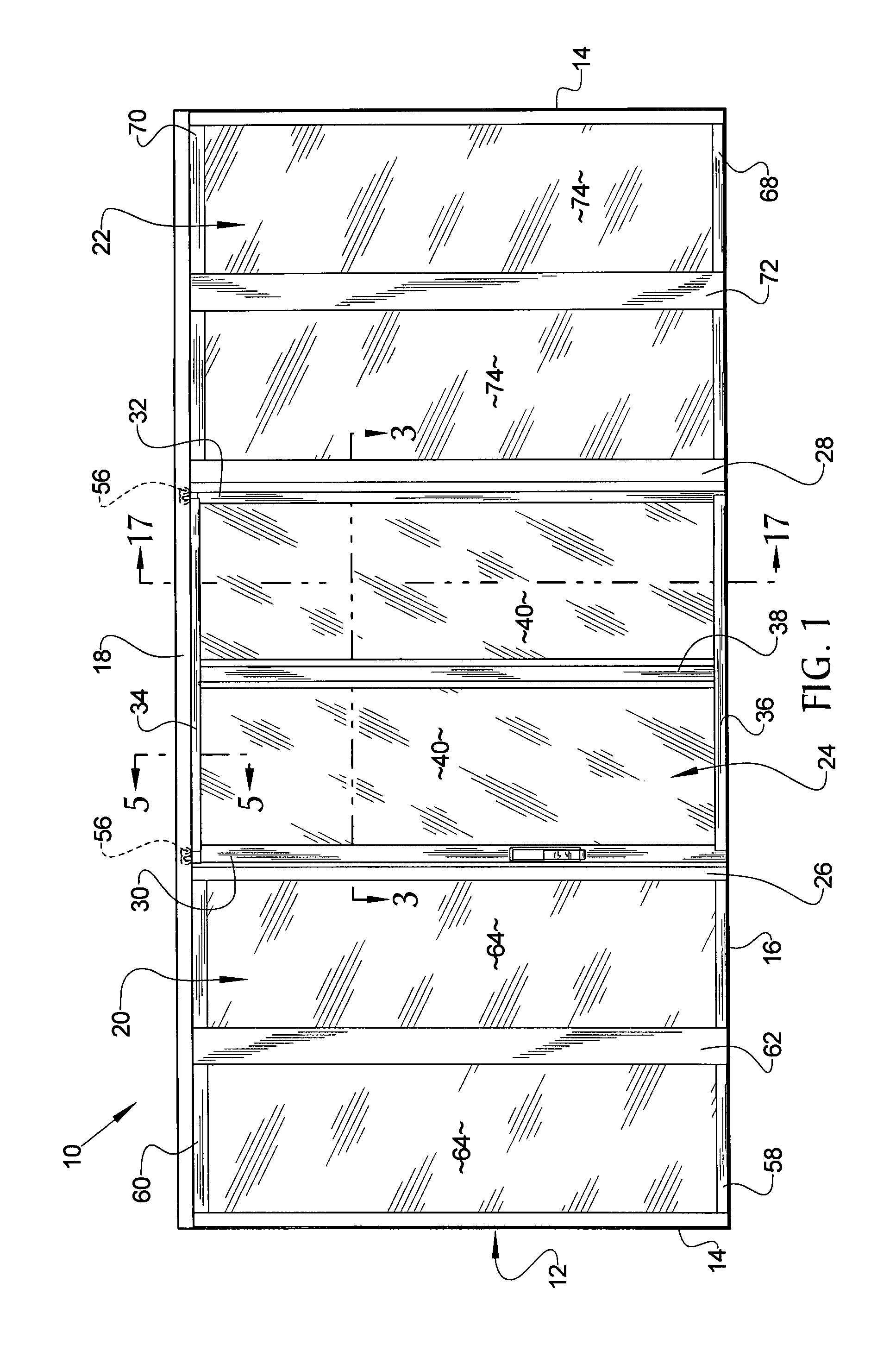
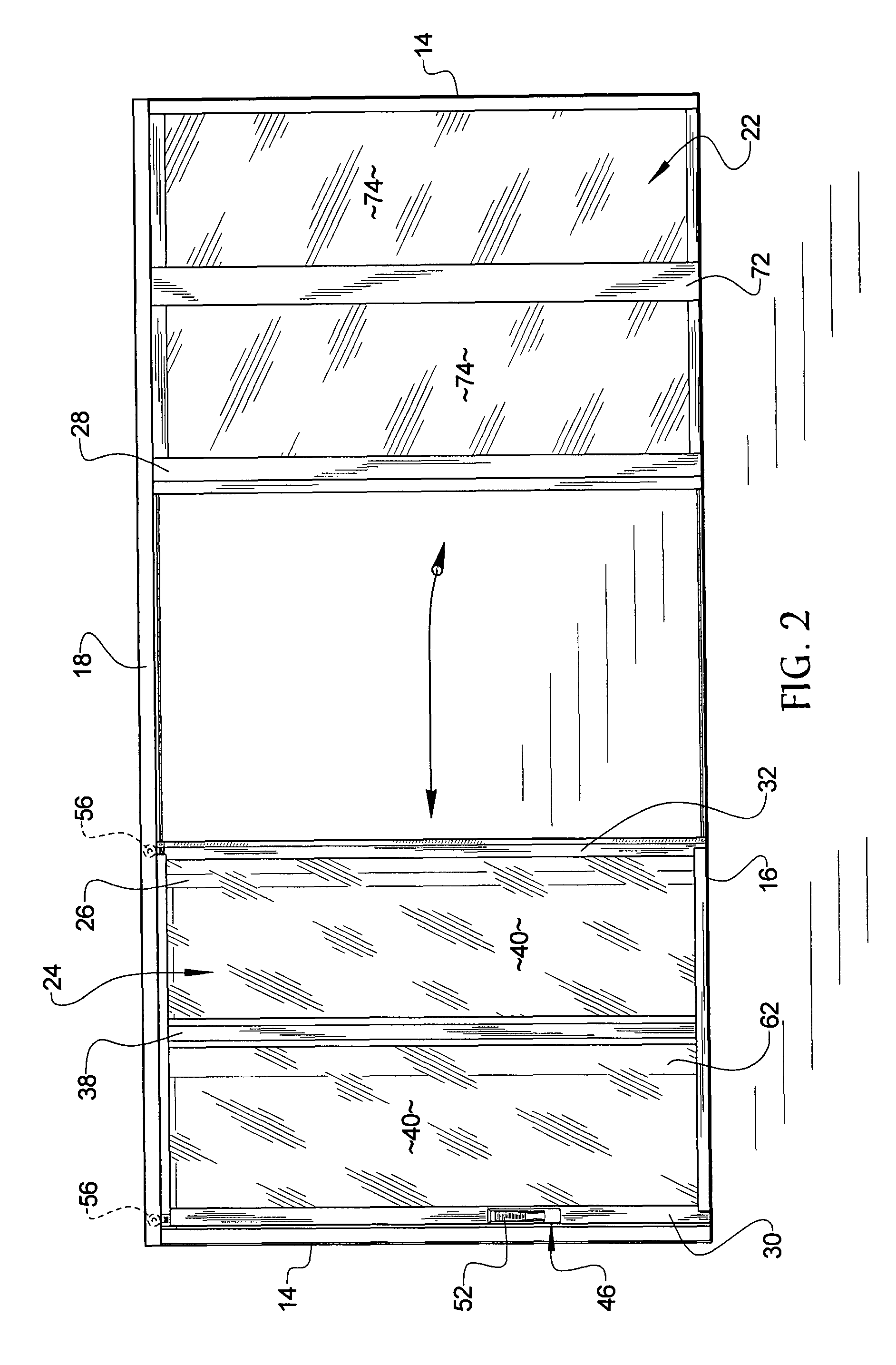
[0037]Referring now to the drawings, it is seen that the sliding door assembly of the present invention, generally denoted by reference numeral 10, is comprised of an overall frame assembly 12 that has a pair of fixed jambs 14 on either side of the frame assembly 12, a sill or threshold 16 that connects the fixed jambs 14 at the lower ends thereof and a header assembly 18 that connects the fixed jambs 14 at the upper ends thereof. The sliding door assembly 10 is illustrated as a three panel system wherein an overlay panel assembly 20 and a non-overlay panel assembly 22 are each fixed and the middle panel assembly 24 is operable, however, the system 10 can be configured as a two panel 20 and 24 assembly, one panel assembly 20 fixed and the other panel assembly 24 operable or other appropriate sliding door configuration. A fix-move mullion 26 extends between the threshold 16 and the header assembly 18 proximate the overlay panel assembly 20 while a move-fix mullion 28 extends between ...


PUM


Abstract

A sliding door assembly has a frame with a movable panel and a fixed panel. The movable panel has a pair of rollers that roll along a header located above the panels with the rollers attached to the movable panel via posts that pass through a channel on the header. The posts pass through a curved section of the channel whenever the movable panel is proximate its closed position and a straight section of channel when the movable panel is traveling laterally. The movable panel presses against a gasket located on the frame components surrounding the movable panel wherein one or more latches press the movable panel against the gasket whenever this panel is in the closed position. Valve is positioned within a weep hole on the threshold in order to prevent water from seeping into the building via the bottom of the door assembly.

Description

BACKGROUND OF THE INVENTION[0001]1. Field of the Invention[0002]The present invention relates to a sliding door assembly wherein the sash of the door seals against the door frame.[0003]2. Background of the Prior Art[0004]The main function of a building's envelope is to prevent water penetration into the interior of a building where such water can cause substantial damage. One problem in any envelope design is the junction between two or more items made from dissimilar materials such as where doors and windows integrate with the main building facade. As each item is made from a different material, each such material thermally expands and contracts at a different rate placing stress on the boundary joint of the dissimilar items. Caulks having a high coefficient of expansion and other techniques are used to address this problem. The caulks resiliently expand and contract and help modulate the expansion and contraction of the materials onto which they are deposited upon.[0005]Operable w...

Claims


Application Information

Patent Timeline
Patent Type & Authority Patents(United States)
IPC IPC(8): E05D15/10
CPCE05D15/0608E05D15/0652E06B3/4627E06B7/14E06B7/26E05D15/0656E05Y2800/12E05Y2800/428E05D15/063E05Y2900/132
Inventor MCDONALD, TIMOTHY J.OSBORNE, JERRYBUNYAN, JERALDGIURIATO, GIORGIO
Owner TIMOTHY J MCDONALD TECH
Why Eureka
Try Eureka