Modular roof structural units and use thereof

a technology of modular roofs and structural units, applied in skylights/domes, lighting and heating apparatus, lighting applications, etc., can solve problems such as inability to meet the needs of construction, and achieve the effects of reducing manufacturing costs, improving strength to weight ratio, and improving material efficiency

Inactive Publication Date: 2013-02-26
HODGETTS CRAIG +1
View PDF12 Cites 8 Cited by
  • Summary
  • Abstract
  • Description
  • Claims
  • Application Information

AI Technical Summary

Benefits of technology

[0008]Advantages of the modules over conventional construction include: more efficient use of materials, improved strength to weight ratio, lower manufacturing cost, and, fewer parts due to semi-monolithic construction.

Problems solved by technology

Such modules are used in remote and rural areas where conventional construction may not be reasonable or possible.

Method used


Image

  • Modular roof structural units and use thereof
  • Modular roof structural units and use thereof
  • Modular roof structural units and use thereof

Examples


Embodiment Construction

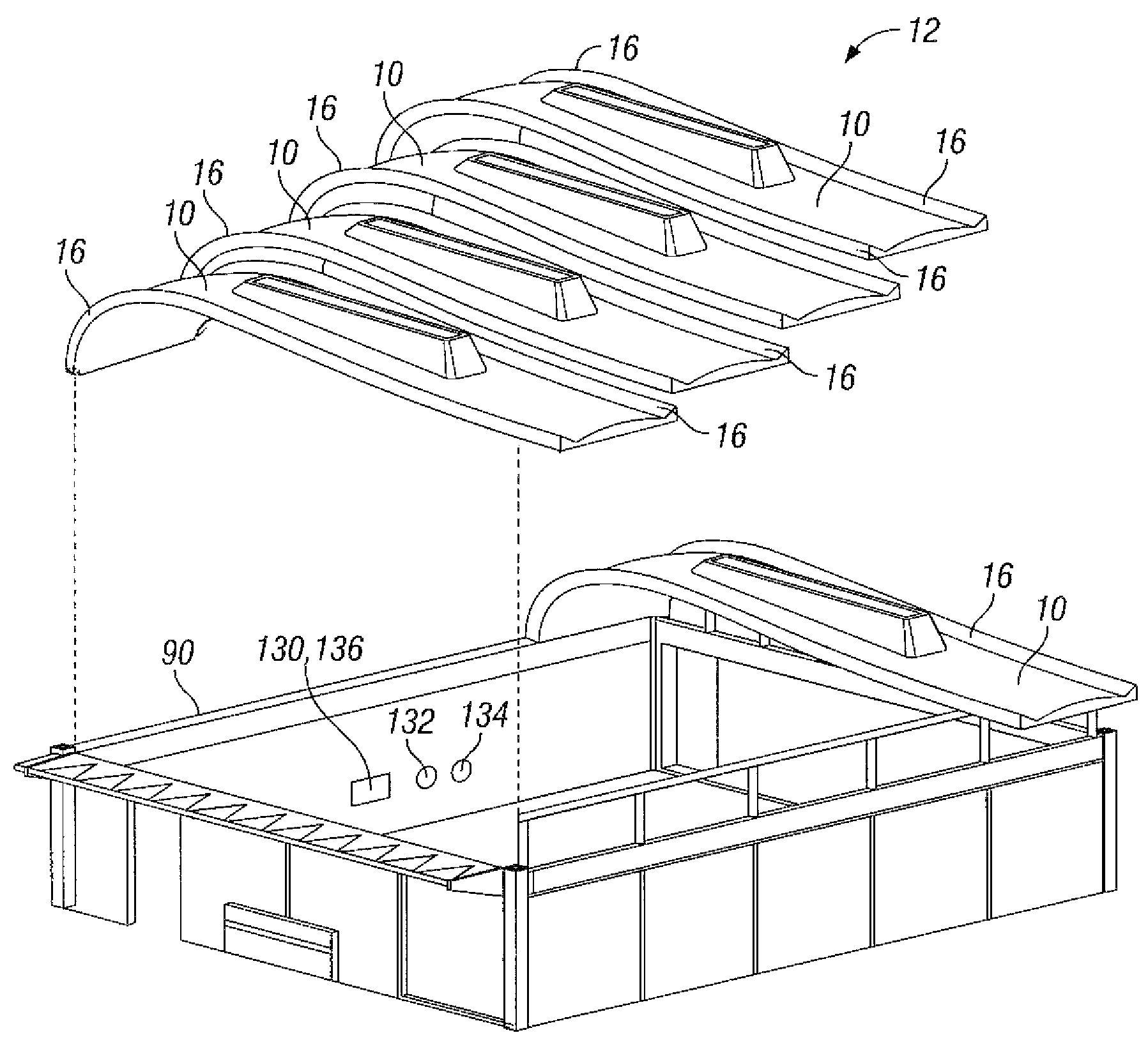
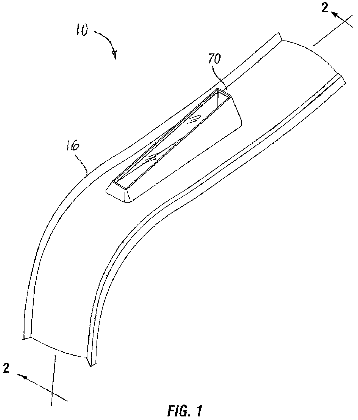
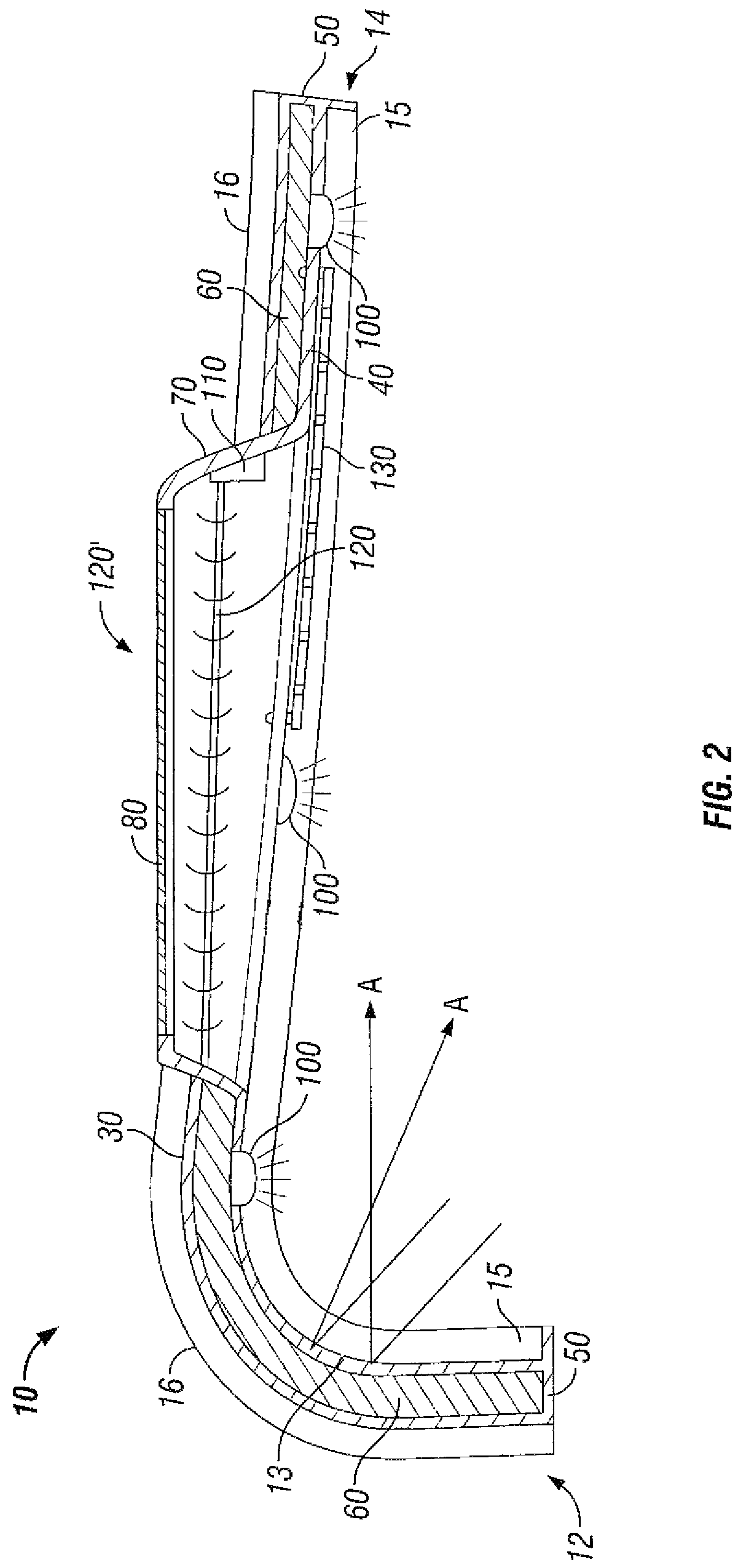
[0019]Referring now to the drawing figures described above, FIG. 1 illustrates a roof unit 10 according to the present disclosure. As illustrated in FIG. 2, unit 10 may be made-up of a pair of spaced-apart rigid fiberglass sheets or skins, an upper skin 30 and a lower skin 40, which may be joined and sealed along their mutual peripheral edges 50 on all sides to form a closed container having a doubly-curved, longitudinally and laterally, monocoque design which may have a thermal insulation material 60 positioned within, that is, between the skins 30, 40. One end 12 of unit 10 may extend downwardly in an arc as shown. A skylight frame 70 may also be formed of fiberglass sheets integral with the skins 30, 40 and may protrude upwardly above the upper skin 30. The skylight frame 70 may support an upwardly facing transparent or semi-transparent window 80 which may be of glass or a glass substitute such as polycarbonate plastic (Lexan®). The upper skin 30 provides raised side edge portion...


PUM


Abstract

A building structure has a generally horizontally disposed modular roof made-up of a plurality of side-by-side roof units which are mutually joined. Each roof unit is constructed as a pair of spaced apart rigid skins shaped in such manner as to eliminate additional supporting structure and which are joined along mutual edges of the pair of skins and forming an interior space filled with a thermal insulator. One end of each of the roof units is curved in a downward arc. A skylight frame protrudes above an upper one of the pair of skins, the frame supporting an upwardly facing window. An electrical circuit includes LED lamps mounted in a lower one of the pair of skins with its illumination directed downwardly. The circuit may also include a motorized shade or a liquid crystal shade for limiting natural light transmission through the window.

Description

CROSS-REFERENCE TO RELATED APPLICATIONS[0001]This application is a continuation based on a prior filed provisional patent application 61 / 437,136, filed on Jan. 28, 2011 and claims international date priority therefrom. The subject matter of application 60 / 603,444 is hereby incorporated herein in its entirety.STATEMENT REGARDING FEDERALLY SPONOSORED RESEARCH OR DEVELOPMENT[0002]Not ApplicableREFERENCE TO SEQUENCE LISTING, A TABLE, OR A COMPUTER PROGRAM USING COMPACT DISC APPENDIX[0003]Not ApplicableBACKGROUND OF THE DISCLOSURE[0004]This disclosure relates to the field of building structures and more particularly to modular roof structural units. Such units may be mutually engaged with a building structure as a number of mutually joined portions resulting in a unitary structure such as a complete roof. Modular buildings and building parts use sectional prefabricated units that may be portions of a building or the entire building and generally consist of multiple modules or sections wh...

Claims


Application Information

Patent Timeline
Patent Type & Authority Patents(United States)
IPC IPC(8): E04H14/00
CPCE04B7/102E04D3/352E04D13/03E04D13/033F21S19/005F21V23/0464
Inventor HODGETTS, CRAIGFUNG, HSINMING
Owner HODGETTS CRAIG
Why Eureka
Try Eureka