Vibration damping device and vehicle

a vibration damping device and vibration technology, applied in mechanical devices, process and machine control, instruments, etc., can solve the problems of inability to achieve optimal vibration damping force, inability to effectively exert vibration damping force generated by vibration application means, and inability to mount linear actuators near the engine or near the vibration-damped position. to achieve the effect of reducing simplifying and speeding up the operation, and preventing the increase of the cost of operation processing

Active Publication Date: 2013-02-26
SINFONIA TECHNOLOGY CO LTD
View PDF12 Cites 5 Cited by
  • Summary
  • Abstract
  • Description
  • Claims
  • Application Information

AI Technical Summary

Benefits of technology

[0017]According to the first invention, such an effect can be obtained that vibrations detected by the vibration detecting means provided at a vibration-damped position can be appropriately damped without receiving an influence of transmission properties from a position mounted with the vibration application means to the vibration detecting means.
[0018]According to the second invention, since an operation for imparting a reverse property is performed by referring to a table only, the operation can be simplified and speeded up. Further, since the operation can be simplified, an increase in cost of an operation processor can be prevented.

Problems solved by technology

However, when retrofitting a linear actuator described in Patent Document 2 as a vibration application means into the vehicle body, the linear actuator cannot be sometimes mounted near the engine or near the vibration-damped position for the reasons of the installation space.
In such a case, although the mounting position of the vibration application means must be spaced from the engine and a vibration-damped position, since the vibration generation source (engine), the vibration application means (linear actuator), and the vibration-damped position (seat section) are different from each other, there is a problem that the optimum vibration damping force cannot be obtained.
That is, the vibration damping force generated by the vibration application means cannot effectively exert an effect on a vibration-damped position, due to an influence of the transmission property from the mounting position of the vibration application means to the vibration-damped position.
Further, since this transmission property can be determined by the rigidity of the vehicle body, the responsivity to the command of the vibration application means, the filter properties of the acceleration sensor, and the like, there is a problem that the amplitude and phase of the vibration damping force to be generated by the vibration application means must be determined in consideration of these transmission properties.

Method used


Image

  • Vibration damping device and vehicle
  • Vibration damping device and vehicle
  • Vibration damping device and vehicle

Examples


first embodiment

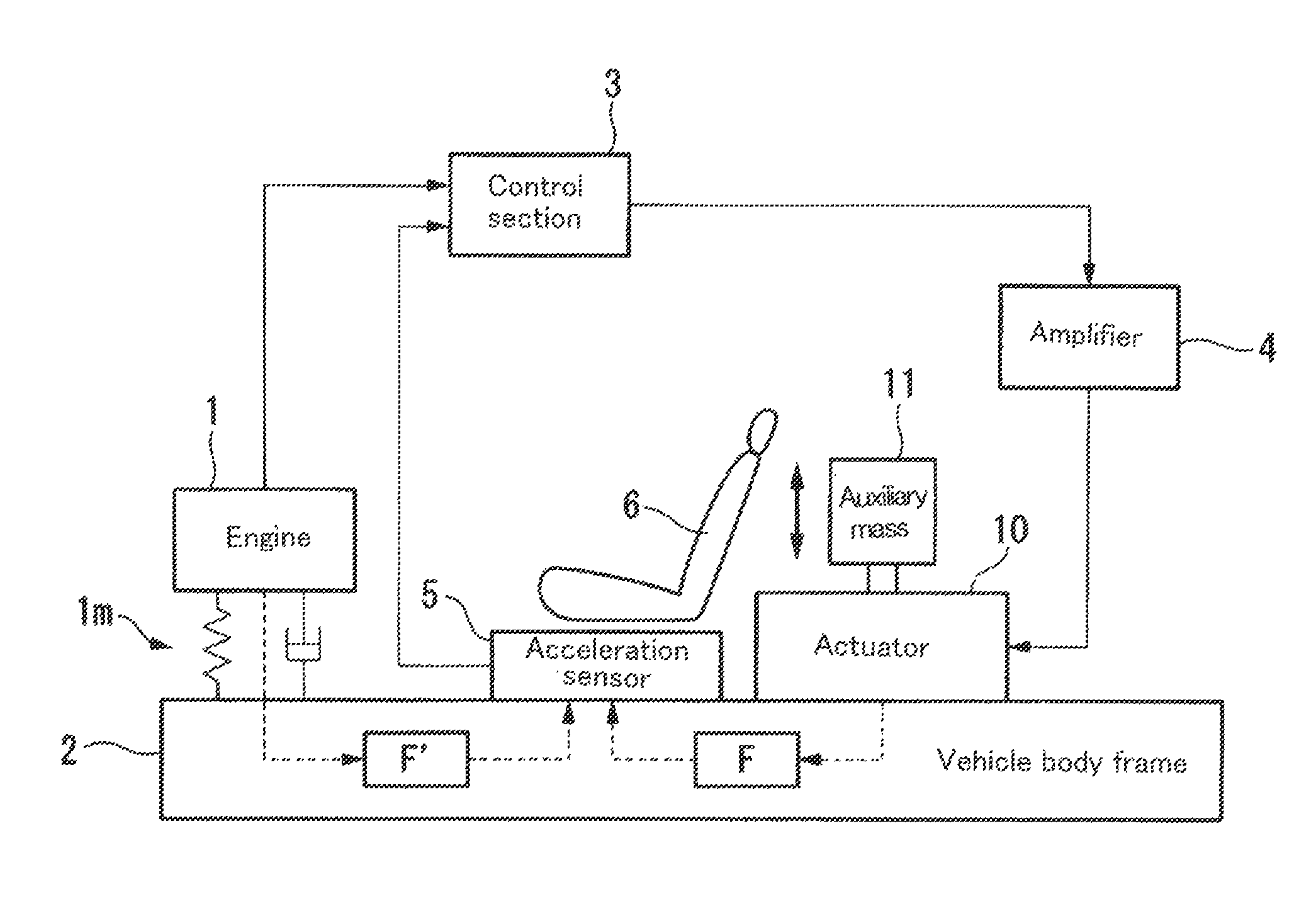
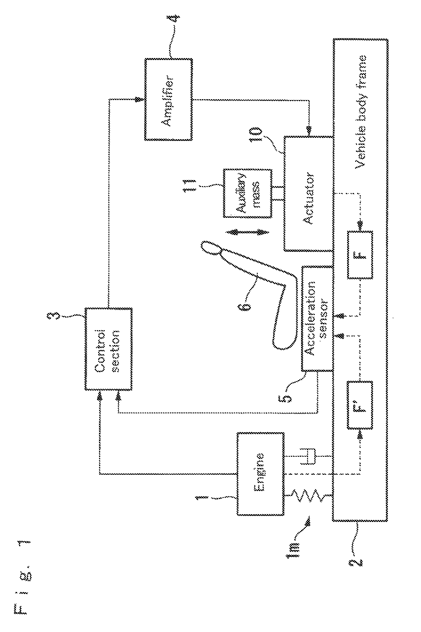
[0024]A vibration damping device according to a first embodiment (first invention) will be described with reference to drawings below. FIG. 1 is a block diagram showing a configuration of the first embodiment. In FIG. 1, the reference numeral 1 denotes an engine (vibration generating source) installed on a vehicle to generate a driving force for traveling a vehicle such as a car and the engine 1 is a generating source of vibrations which are generated in the vehicle. The reference numeral 10 denotes a linear actuator (hereinafter referred to as “actuator” (vibration application means)), which includes an auxiliary mass 11 and generates a vibration damping force for damping vibrations generated in a vehicle, by a reaction obtained by vibrating the auxiliary mass 11. The reference numeral 2 denotes a body frame of a vehicle, in which the engine 1 is installed by an engine mount 1m and the actuator 10 is mounted at a predetermined position.

[0025]Here, the actuator 10 damps and controls...

second embodiment

[0038]A vibration damping device of a second embodiment according to the second invention will be described while omitting descriptions and drawings by denoting the same reference numerals to the same portions as in the above-described first embodiment. FIGS. 1, 2 and 4 are the same as in the first embodiment, and explanation will be made with reference to FIG. 5 instead of FIG. 3. In the vibration damping device according to the second embodiment, the control section 3 according to the first embodiment is replaced by a control section 103, which will be described below.

[0039]FIG. 5 is a control block diagram showing a detailed configuration of the control section 103. The control section 103 inputs and outputs signals of the acceleration sensor 5 and engine pulse signals of the engine 1, and outputs a vibration application command to the amplifier 4. It is noted that a control system explained here is based on an adaptive control algorithm utilizing the least squares method in whic...


PUM


Abstract

The present invention provides a vibration damping device which can enhance a vibration damping effect even in a case where a vibration damping target position and a vibration damping force generation position are different from each other. The vibration damping device includes a vibration detecting unit for detecting a vibration which is caused by a vibration generating source and is transmitted to a position at which the vibration is to be damped; a vibration application unit which generates a vibration damping force to cancel the vibration, and is provided at a position different from the position at which the vibration is to be damped; a vibration application command generating unit for outputting a vibration application command to generate the vibration damping force in the vibration application unit, based on the vibration detected by the vibration detecting unit; and a vibration application command correcting unit which imparts to the vibration application command, a reverse property of a vibration damping force transmission path including a vibration transmission property from a position at which the vibration application unit is mounted to the position at which the vibration is to be damped, and then outputs the vibration application command to the vibration application unit.

Description

TECHNICAL FIELD[0001]The present invention relates to a vibration damping device for damping vibrations to be generated and a vehicle including the vibration damping device.BACKGROUND ART[0002]With respect to vibrations of a vehicle generated by the output torque variation of the vehicle engine, a vibration damping device has been known which actively apply vibrations by causing a vibration application means to generate a vibration damping force in order to damp vibrations of a vehicle. Specifically, as such a vibration damping device, a damping device has been proposed which comprises a linear actuator serving as a vibration application means provided in an engine as a vibration generating source, a means for detecting the number of revolutions of the engine as the vibration generating source, a vibration detecting means for detecting vibrations at the position at which the vibrations are to be damped, i.e., a vibration-damped position, and an adaptive control algorithm for outputt...

Claims


Application Information

Patent Timeline
Patent Type & Authority Patents(United States)
IPC IPC(8): G01M15/12
CPCG05D19/02F16F15/002
Inventor SATO, YUSHIMORIYA, HIDEAKIITO, TAKEOFUJII, TAKAYOSHIFUKUNAGA, TAKASHINAKANO, KATSUYOSHINAKAGAWA, HIROSHIKATADA, HIDETOSHITOMIZAKI, TAKESHIONOUE, TAKASHIMURAGISHI, YASUSHI
Owner SINFONIA TECHNOLOGY CO LTD
Why Eureka
Try Eureka