Mini-tiller tensioning wheel mechanism

A tensioning wheel and tiller technology, applied in the field of tension devices, can solve the problem that it is difficult to accurately control the pushing amount of the belt by the tensioning wheel, the tension of the belt cannot reach the best state, and the precise control of the tensioning wheel cannot be achieved. and other problems, to achieve the effect of high tension, not easy to drift, and stable power

Inactive Publication Date: 2015-01-14
重庆兆方工贸有限公司
View PDF9 Cites 0 Cited by
  • Summary
  • Abstract
  • Description
  • Claims
  • Application Information

AI Technical Summary

Problems solved by technology

The main disadvantages of the tensioning pulley in the prior art are as follows: when the operator turns the handle to rotate the tensioning pulley, the position of the tensioning pulley cannot be accurately controlled, and the pushing amount of the tensioning pulley to the belt is difficult to accurately control , the displacement of the tensioning wheel is too large, causing the belt to be overloaded and causing greater wear to the belt; or, the displacement of the tensioning wheel is too small, the tension of the belt cannot reach the best state, and the torque Large loss during belt transmission

Method used


Image

  • Mini-tiller tensioning wheel mechanism
  • Mini-tiller tensioning wheel mechanism

Examples


Embodiment Construction

[0018] The preferred embodiments of the present invention will be described in detail below with reference to the accompanying drawings.

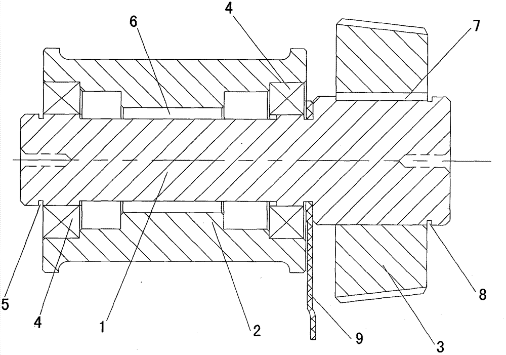
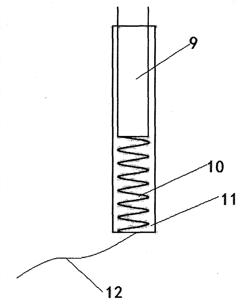
[0019] Such as figure 1 Shown is the structural representation of micro-tiller tension wheel mechanism of the present invention; figure 2 Shown is a structural schematic diagram of the supporter of the micro tiller tensioner mechanism of the present invention; a micro tiller tensioner mechanism of the present invention includes a support frame 9 and a tension wheel 2 that abuts on the transmission belt, and also includes a speed reduction shaft 1. The deceleration shaft is connected to the support frame 9, the tension wheel 2 is set on one end of the deceleration shaft 1 through the bearing 4, and the other end of the deceleration shaft 1 extends into the gearbox and is connected with Friction disc 3, said friction disc 3 is used for speed reduction near the transmission shaft.

[0020] In this embodiment, the micro tillage machine tensi...


PUM


Abstract

The invention discloses a mini-tiller tensioning wheel mechanism, which comprises a support frame and a tensioning wheel abutted against a transmission belt; the mini-tiller tensioning wheel mechanism also comprises a speed reducing shaft, wherein the speed reducing shaft is connected onto the support frame, the tensioning wheel is arranged at one end of the speed reducing shaft through a bearing in a sheathing way, the other end of the speed reducing shaft extends into a gearbox and is connected with a friction disc, and the friction disc is close to a transmission shaft and is used for speed reduction. The mini-tiller tensioning wheel mechanism has the advantages that the tensioning wheel and the friction disc are arranged on the speed reducing shaft, the tensioning wheel can realize the tensioning on a belt through the vertical or transverse movement of the speed reducing shaft, meanwhile, the rotating speed of an output shaft can be reduced through the friction disc, and the speed reducing goal is achieved, so the tensioning wheel can realize the self regulation through the fastening and loosening along with the operation process of the belt or a chain, the proper damping is ensured, the vibration is reduced, and the equipment operation stability is ensured.

Description

technical field [0001] The invention belongs to the technical field of devices for changing the tension of belts, ropes or chains, and in particular relates to a tension wheel mechanism of a tiller. Background technique [0002] With the development of my country's agricultural modernization, micro-tillers have entered many farmers' families. Micro-tillers can reduce farmers' labor intensity and improve labor productivity. There are many structures for power transmission. Belt drive is a common structure of micro tillage machine, which is to set a transmission belt between the driving pulley and the driven pulley, and the driving pulley drives the driven pulley to rotate through the transmission belt, so as to transmit the power to the driven pulley . A tension pulley needs to be set between the driving pulley and the driven pulley. When the tension pulley rotates, the belt is pushed to tension the belt (tighten the belt), prevent it from slipping, and reduce the loss of to...

Claims


Application Information

Patent Timeline
Patent Type & Authority Applications(China)
IPC IPC(8): F16H7/08
CPCF16H7/08F16H2007/0842
Inventor 王德雄杨洪
Owner 重庆兆方工贸有限公司
Why Eureka
Try Eureka