Dental floss

a technology for dental flossing and distal ends, which is applied in the field of improved dental flossing equipment, can solve the problems of difficult to pass round threadlike floss between two adjacent teeth, difficult to hold the distal end of the floss which can painfully ‘strangle’, and conventional flossing regimen does not provide initial or immediate positive reinforcement to the floss trainee. , to achieve the effect of convenient manufacture and commercialization

Inactive Publication Date: 2013-02-26
LORCH LEONARD G
View PDF87 Cites 3 Cited by
  • Summary
  • Abstract
  • Description
  • Claims
  • Application Information

AI Technical Summary

Benefits of technology

[0013]The edible substrate may be a pullulan or gelatin base. A pullulan substrate provides a fairly rapid rate of dissolution while a gelatin-based substrate dissolves less quickly and may be desired as well for that reason so as to allow more time for flossing while concurrently communicating a taste and / or cooling sensation to the user during the continued flossing session.
[0029]A further object of the present invention is to provide a dental device which is easy to manufacture and commercialize by pre-existing dental floss manufacturers and marketers and retailers of global-branded floss products to better serve end users.

Problems solved by technology

It is often difficult to pass the round threadlike floss in between two adjacent teeth due to the resistance encountered by the tooth's side edges.
Similarly, children as well as many adults find it hard to hold the distal ends of the floss which can painfully ‘strangle’ the fingers around which they are wrapped during use.
Furthermore, the conventional flossing regimen does not provide any initial or immediate positive reinforcement to the floss trainee other than of course any oral encouragement from an instructor.
Even in dedicated users having a flossing regimen, such a lack of encouragement or an inducement to continue, can be a resulting cause of reduced flossing over time.
However, in some individuals, the engagement of the edible substrate to the planar substrate may impart a difficulty in the insertion of the floss to translatably engage in between two adjacent teeth.

Method used


Image

  • Dental floss
  • Dental floss
  • Dental floss

Examples


Embodiment Construction

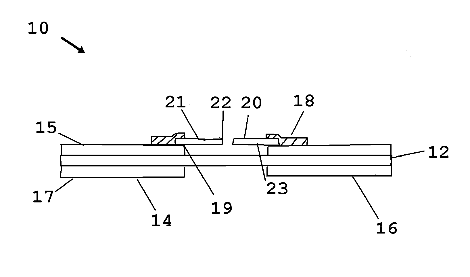
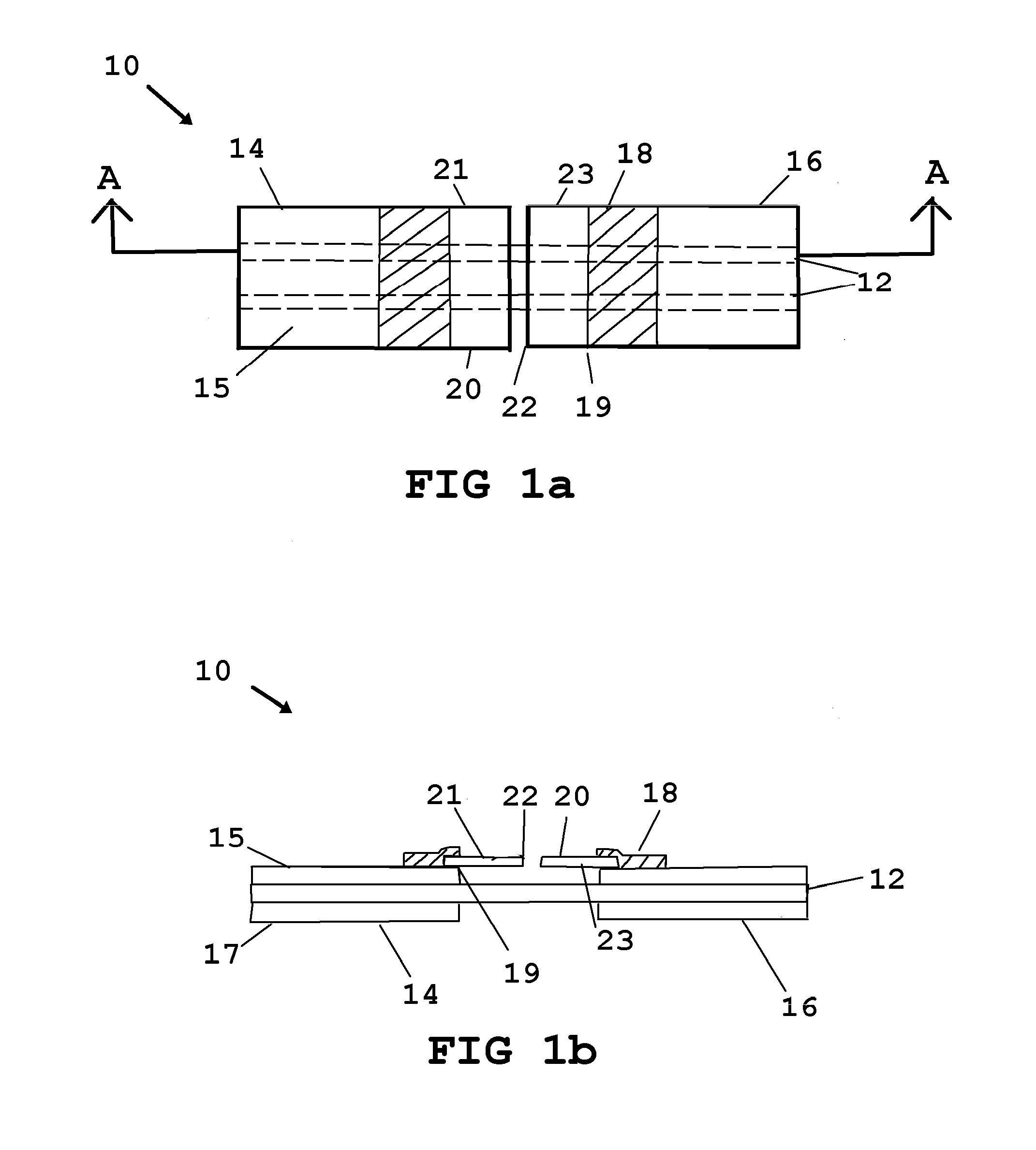
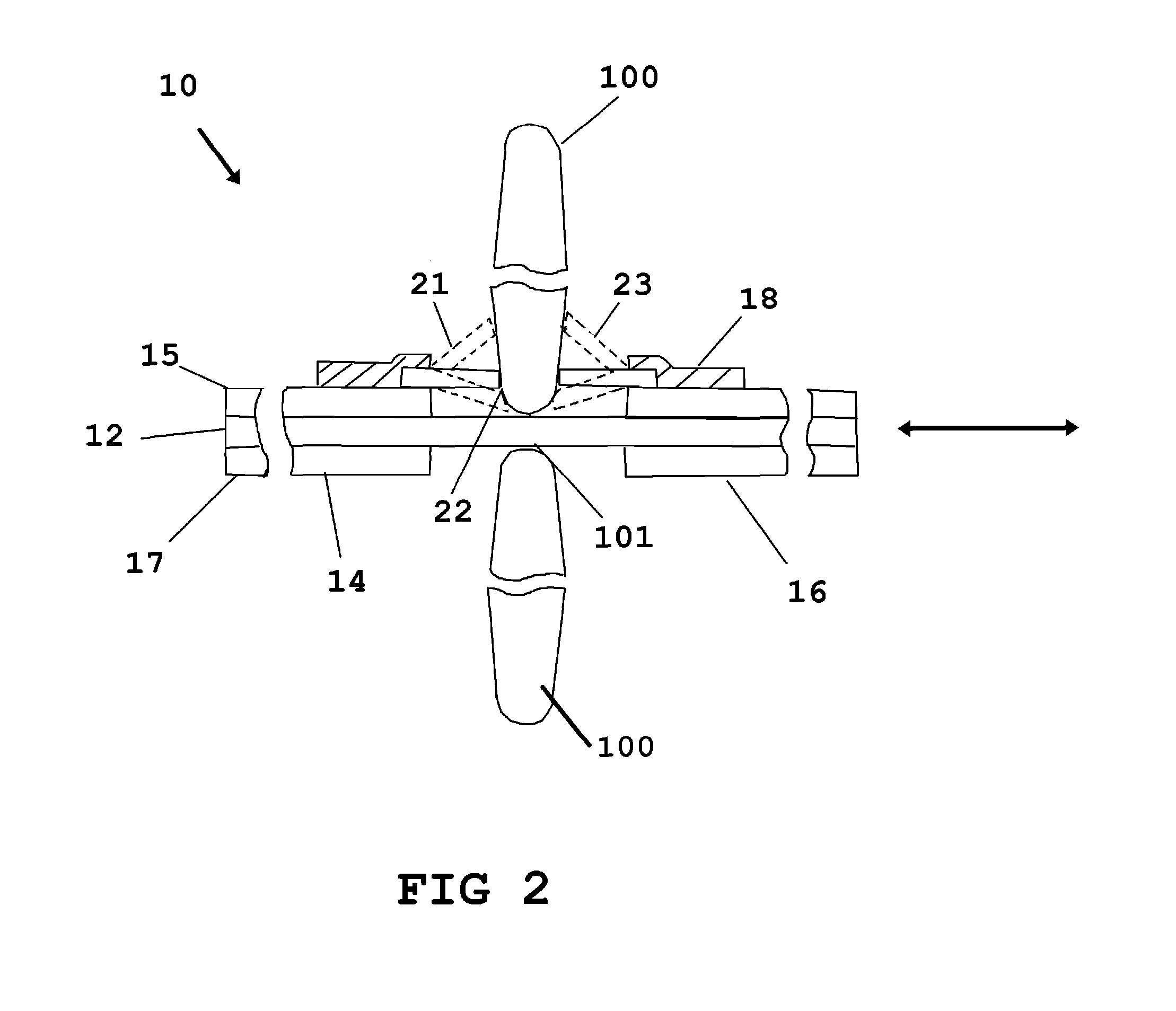
[0058]Now referring to drawings in FIGS. 1-16, wherein similar components are identified by like reference numerals, there is seen in FIG. 1a a particularly preferred mode of the device 10. In this mode a left and right handle 14 and 16 are shown engaged to flossing substrate 12 communicating therebetween and providing means for engagement with the fingers of a user during use.

[0059]Also extending from an attachment point to each handle 14 and 16, from the same respective edge thereof where the flossing substrate 12 extends, are a first portion 21 and second portion 23 of a dissolvable and edible substrate 20 material which is adapted to dissolve when contacted by saliva coated teeth and gums. The edible substrate 20 portions 21 and 23, are sized to extend from their attachment point to their respective handle 14 and 16, a distance less than the total length of the flossing substrate 12 extending therebetween. Consequently when the handles 14 and 16 are engaged by the figures of a u...


PUM


Abstract

A dental floss apparatus for cleaning the gaps between adjacent teeth which is comprised of a pair of handles that are configured for engagement with the fingers with strands of flossing substrate extending therebetween. The flossing substrates are spaced from each other, running substantially parallel and extending within an opening formed between the ends of the handles, with tension maintained by the user through employment of the handles. A dissolvable substrate is positioned within this opening through an engagement with one or both of the handles or the flossing substrate, and upon contact with the surface of the teeth, dissolves, and deposits a residue on the surface of the teeth and the surrounding area of the mouth. The dissolvable substrate may be formed of two substrate pieces with a central gap between them defining a means for targeting insertion of the substrate between adjacent teeth and may be colorized or fluorescent, and have an additive material such as mouthwash, breath freshener, cooling agent, or flavor.

Description

BACKGROUND OF THE INVENTION[0001]1. Field of the Invention[0002]The present invention relates to an improved dental flossing apparatus. More particularly it relates to a flossing device and method which is easier and more comfortable to employ than conventional floss products and additionally provides a means to induce increased use through the provision of a gustatory sensation during use as means to encourage regular flossing by the user as part of an ongoing dental hygiene regime.[0003]2. Prior Art[0004]Virtually all dental health practitioners and professionals of the like recommend the use of dental floss for the removal of interdental plaque and particulate from between teeth and under the gum line. These are places that a toothbrush cannot reach and are common initiation sites for tooth decay and gum disease when not cleaned regularly and properly.[0005]Conventional threadlike floss maintains many discouraging aspects to a new or ill-practiced user. It is often difficult to p...

Claims


Application Information

Patent Timeline
Patent Type & Authority Patents(United States)
IPC IPC(8): A61C15/00
CPCA61C15/041A61C15/046A61C15/043
Inventor LORCH, LEONARD G.
Owner LORCH LEONARD G
Why Eureka
Try Eureka