Pneumatic tire

a technology of pneumatic tires and spherical plates, which is applied in the direction of vehicle components, non-skid devices, transportation and packaging, etc., can solve the problems of increasing the area of wear, causing cracks on the groove bottom of the thin groove, and increasing the amount of wear in the area, so as to achieve the effect of ensuring the anti-wear performance of the entire shoulder land portion, reducing the stiffness in the base area of the sacrifice portion, and improving the anti-wear performan

Active Publication Date: 2013-02-26
TOYO TIRE & RUBBER CO LTD
View PDF5 Cites 1 Cited by
  • Summary
  • Abstract
  • Description
  • Claims
  • Application Information

AI Technical Summary

Benefits of technology

[0006]The present invention has been made in light of the above circumstances and an object thereof is to provide a pneumatic tire which reduces the partial wear while maintaining the durability in the shoulder land portion.
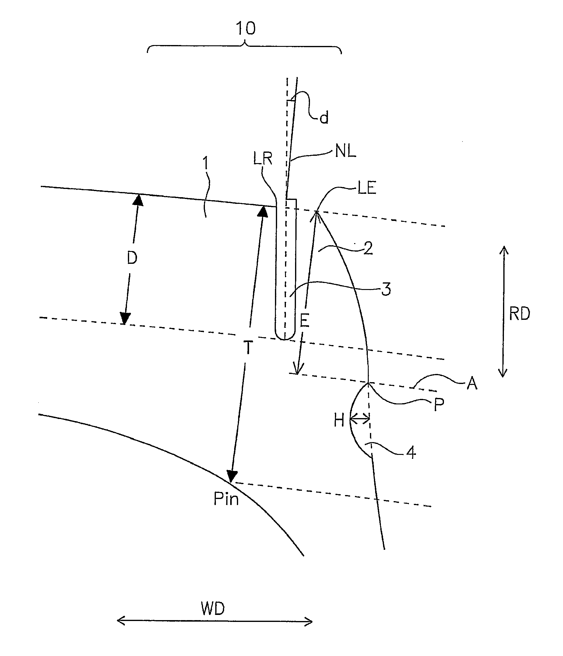
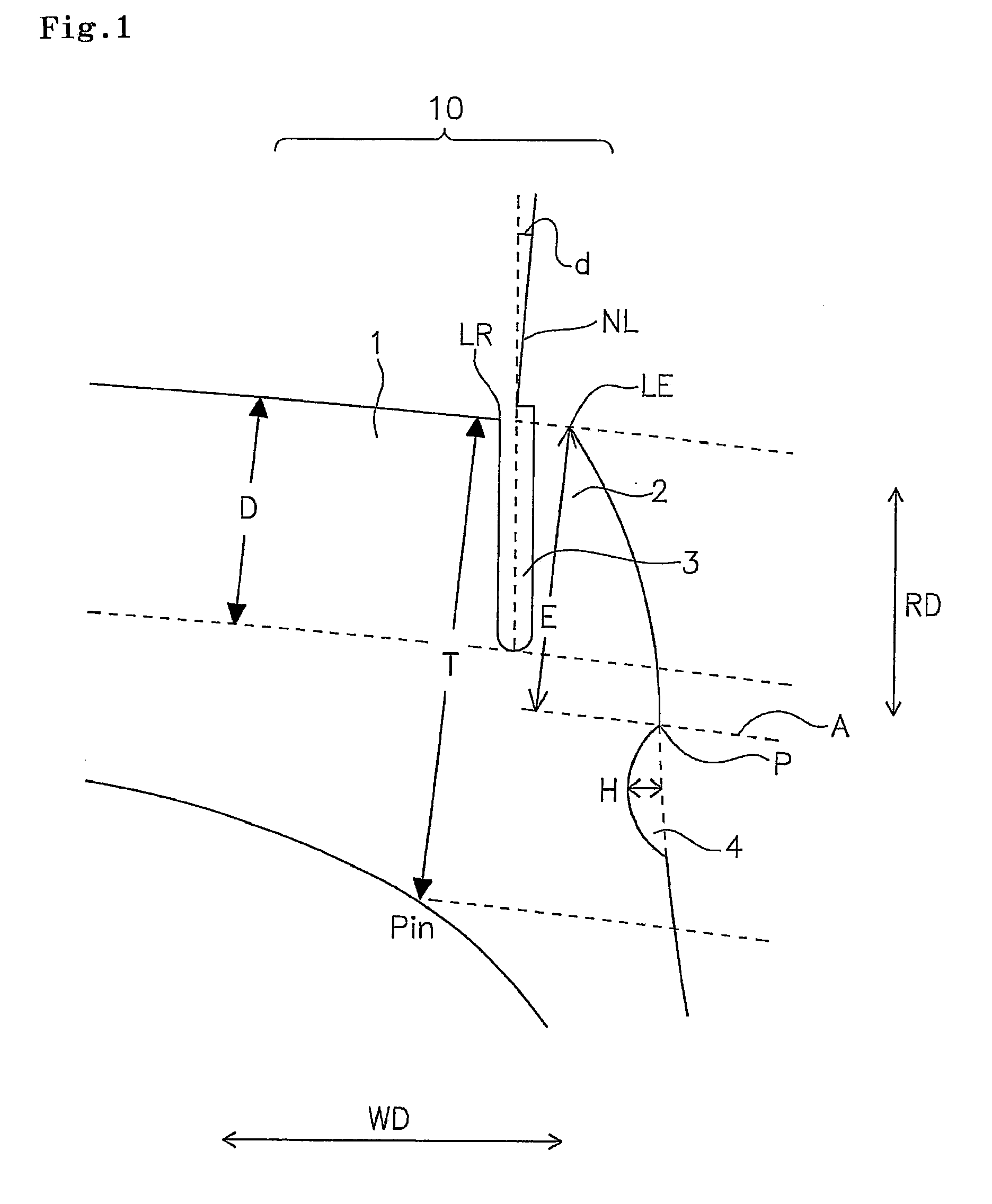
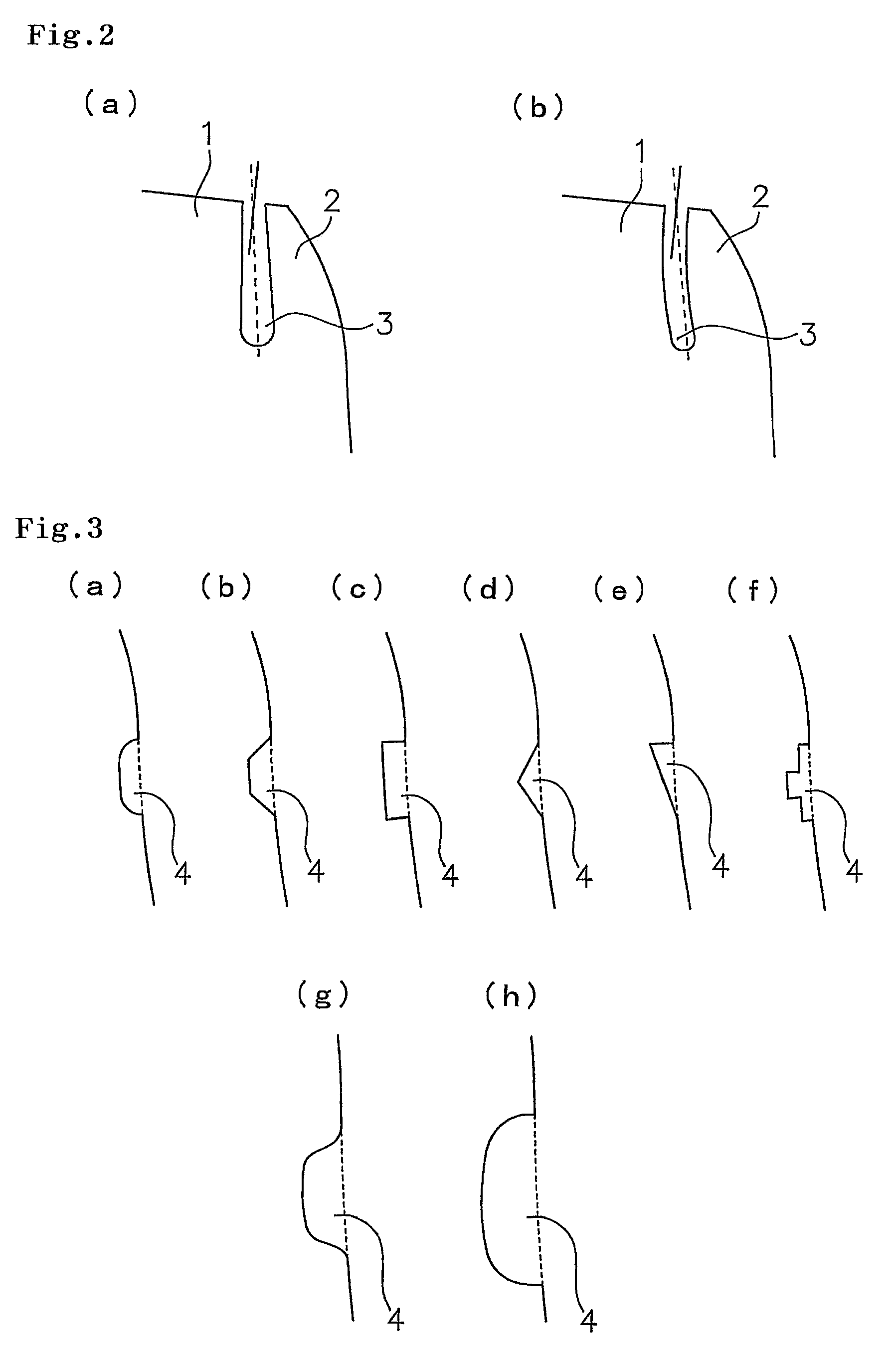
[0008]In the above-described pneumatic tire, the thin groove extending in the circumferential direction of the tire on the shoulder land portion is arranged so as to be perpendicular to or inclined outward to the groove bottom from the tread surface as viewed in the cross-section of the meridian direction of the tire. With this arrangement, the stiffness of the main land portion can be ensured and the anti-wear performance of the entire shoulder land portion can be improved. Furthermore, the stiffness in a base area of the sacrifice portion can be appropriately reduced. Even when the sacrifice portion is deformed during running on the road, the stress is prevented from converging on the groove bottom of the thin groove. Thus, cracks can be prevented from occurring on the groove bottom of the thin groove. Further by arranging the buttress groove to position at the inner side than the groove bottom of the thin groove with respect to a normal line of the tread surface as viewed in the radial direction of the tire, at the same time, at the outer side than the inner surface of the tire as viewed in the radial direction of the tire, the load applied to the shoulder land portion is reduced while avoiding the stiffness of the sacrifice portion from being reduced. As a result, in the above pneumatic tire, partial wear can be reduced while maintaining the durability of the shoulder land portion of the tire.
[0009]In the above pneumatic tire, when defining the depth “H” of the buttress groove, the depth “H” is preferably set to be 0.1D<H<0.2D. With this arrangement, the stiffness of the sacrifice portion can be satisfactorily ensured while reducing the load applied to the shoulder land portion during running on the road.

Problems solved by technology

As a result, there may be caused a problem of partial wear in which, compared to other land portion in the tread surface, an amount of wear becomes larger in the area adjacent to the contact edge of the shoulder land portion.
On the other hand, too high stiffness of the sacrifice portion causes stress to converge on the groove bottom of the thin groove due to the deformation of the sacrifice portion during running on the road.
This causes cracks to be generated on the groove bottom of the thin groove.
As a result, even in an initial to middle stage of use of the tire, the sacrifice portion may be broken.
As a result, an amount of wear becomes larger in an area of the main land portion at the thin groove side edge (in the main land portion, in an area adjacent to an edge line formed by the thin groove and the main land portion therebetween) resulting in a problem of partial wear.
Further, the method does not define the configuration of the buttress groove.
Depending on the configuration of the buttress groove, cracks may occur on the buttress groove.
As a result, the partial wear reduction effect may be degraded.

Method used


Image

  • Pneumatic tire
  • Pneumatic tire
  • Pneumatic tire

Examples


examples

[0025]Example and Comparative Examples that particularly demonstrate the structure and effect of the present invention are described below. Items to be evaluated are as described below and measurement was conducted on each of the Example and Comparative Examples.

Anti-Partial Wear Performance

[0026]Test tires (295 / 75R22.5) were mounted to front wheels of tractor of a line-hauler. After running 80,000 Km on a dry road, volume of partial wear was measured. Inverse number of the measured volume was used for evaluation of anti-partial wear performance. When defining the value of Comparative Example 1 as 100, the evaluation is indicated with index number. The larger number means the more preferable anti-partial wear performance.

example 1

[0027]Test pneumatic tires (α=5°, D=15 mm, E=20 mm, T=45 mm, H=2.5 mm) having shoulder land portions structure shown in FIG. 1 were produced. Using test pneumatic tires, the above test was conducted and evaluated. Test result is shown in Table 1.


PUM


Abstract

The object of the present invention is to provide a pneumatic tire which reduces the partial wear while maintaining the durability in the shoulder land portion. In order to achieve the above object, the thin groove extending in the circumferential direction of the tire on the shoulder land portion is arranged so as to be perpendicular to or inclined outward to the groove bottom from the tread surface as viewed in the cross-section of the meridian direction of the tire, and the buttress groove is arranged to position at the inner side than the groove bottom of the thin groove with respect to a normal line of the tread surface as viewed in the radial direction of the tire, at the same time, at the outer side than the inner surface of the tire as viewed in the radial direction of the tire.

Description

BACKGROUND OF THE INVENTION[0001]1. Field of the Invention[0002]The present invention relates to a pneumatic tire which has a tread surface including a shoulder land portion extending in a circumferential direction of the tire, and a thin groove extending in a circumferential direction of the tire located at, as viewed in a width direction of the tire, the outer side than a contact edge of the shoulder land portion; the thin groove partitioning the shoulder land portion into a main land portion located at the inner side and a sacrifice portion located at the outer side of shoulder land portion, and the tire including a buttress groove extending in a circumferential direction of the tire located at the outer side than the contact edge of the shoulder land portion.[0003]2. Description of the Related Art[0004]In a pneumatic tire, generally, in an area adjacent to a contact edge of a shoulder land portion in a tread surface, the contact pressure tends to increase during running. As a re...

Claims


Application Information

Patent Timeline
Patent Type & Authority Patents(United States)
IPC IPC(8): B60C11/12B60C13/02
CPCB60C11/01
Inventor MIYAKE, AKINORI
Owner TOYO TIRE & RUBBER CO LTD
Why Eureka
Try Eureka