Pressure reduction in high pressure processing system

a processing system and high-pressure technology, applied in the direction of fluid pressure control, piston pumps, instruments, etc., can solve the problems of fast wear of valve sealing surfaces, high velocity, and high speed of pressure let down systems

Active Publication Date: 2022-09-06
STEEPER ENERGY
View PDF20 Cites 0 Cited by
  • Summary
  • Abstract
  • Description
  • Claims
  • Application Information

AI Technical Summary

Benefits of technology

[0008]The object of the present invention is to therefore provide for a pressure reduction unit, a pressure reduction arrangement as well as a method of operating such units and arrangements that increases the reliability of the pressure reduction system and hence the reliability of the process system into which it is implemented.DESCRIPTION OF THE INVENTION
[0010]By applying a pressure reduction device in the manner defined it is possible to achieve a reduced flow velocity and hence reduce the wear of the parts, resulting in a more reliable pressure reduction system and a more reliable overall processing system.

Problems solved by technology

However, whereas such control valves and / or orifices are commonly used for smaller ΔP and often clean fluids.
A disadvantage limiting such systems is that they are two-dimensional.
If used in higher ΔP applications the velocities either gets very high and the pressure let down system is worn out very quickly due to erosion even when using hard ceramic coatings such as tungsten carbide or gets excessively expensive due to multiple steps required for such two-dimensional pressure let down systems.
Further when used in a process where an abrasive substance is processed, it result in an even faster wear of the valve sealing surfaces, resulting in frequent requirement for refurbishing or changing of the valves.
The disadvantage of such systems is that the pressure loss in the first stage needs to be relatively small in order to not fluctuating the process pressure and that the shut off valves must be operated frequently and incur rapid wear, particularly at high pressure when cycles are short.
Further such type of device does not operate in a truly continuous manner.
Common for high pressure process equipment using these known methods and equipment is that the wear may still be significant due to the content of abrasive material in the flowing liquid and since the flow velocity over the pressure reduction devices is significant.
As a result the known pressure reduction systems may be unreliable and hence making the entire high pressure processing system unreliable.

Method used


Image

  • Pressure reduction in high pressure processing system
  • Pressure reduction in high pressure processing system
  • Pressure reduction in high pressure processing system

Examples


Embodiment Construction

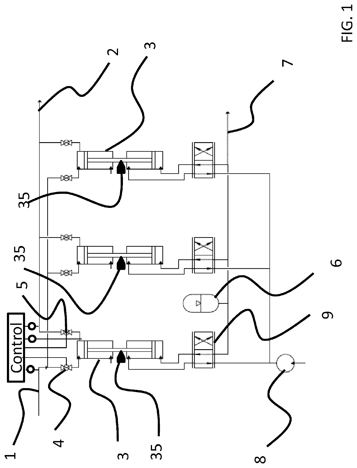
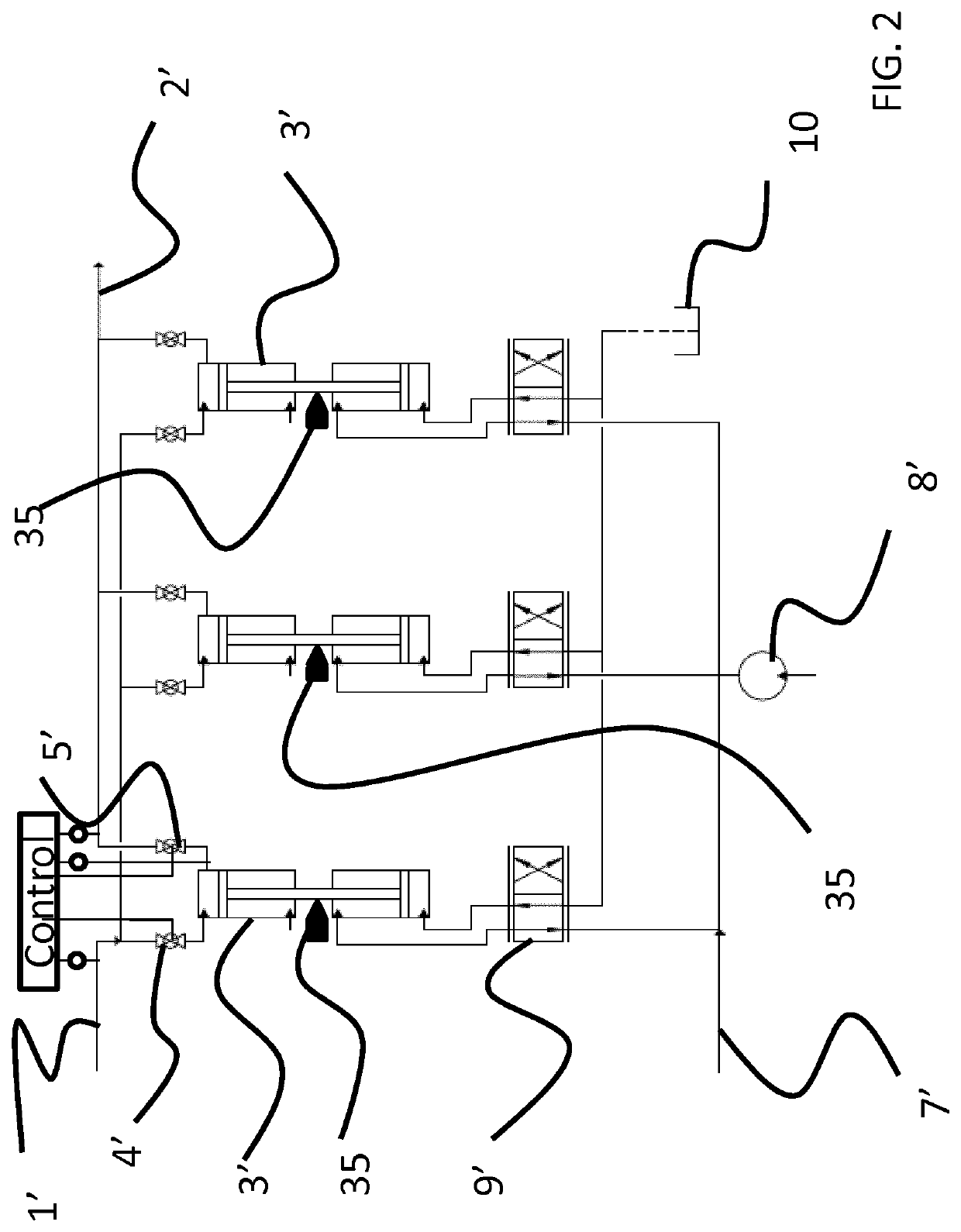
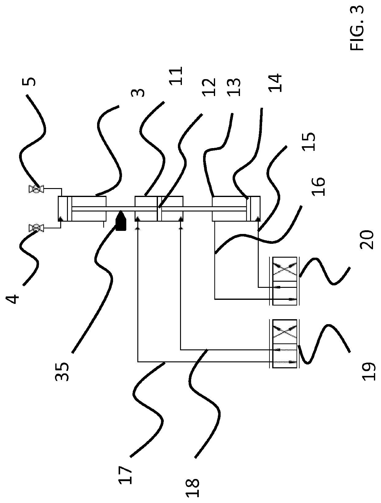
[0009]According to one aspect of the present invention the objective of the invention is achieved through a pressure reduction unit for use in processing equipment handling high pressure fluid, where the pressure reduction unit comprises at least one inlet and an outlet, the pressure reduction unit being adapted to receive a pressurized fluid at process pressure level at the inlet, being adapted to isolate the received pressurized fluid from the upstream process and from the outlet and being adapted to reduce the pressure of the fluid to a lower predetermined level and further being adapted to output the fluid through the outlet while still isolated towards the upstream process.

[0010]By applying a pressure reduction device in the manner defined it is possible to achieve a reduced flow velocity and hence reduce the wear of the parts, resulting in a more reliable pressure reduction system and a more reliable overall processing system.

[0011]In an embodiment the pressure reduction unit ...


PUM

PropertyMeasurementUnit
pressureaaaaaaaaaa
reaction temperatureaaaaaaaaaa
temperatureaaaaaaaaaa

Abstract

The invention relates to a pressure reduction unit for use in processing equipment handling high pressure fluid, where the pressure reduction unit comprises at least one inlet and an outlet, the pressure reduction unit being adapted to receive a pressurized fluid at process pressure level at the inlet, being adapted to isolate the received pressurized fluid from the upstream process and from the outlet and being adapted to reduce the pressure of the fluid to a lower predetermined level and further being adapted to output the fluid through the outlet while still isolated towards the upstream process.

Description

FIELD OF THE INVENTION[0001]The present invention relates to the area of pressure reduction systems, in particular pressure reduction systems for use in high-pressure continuous processing systems, where a need for reduction of the high process pressure to a lower pressure is present.BACKGROUND OF THE INVENTION[0002]Numerous applications of high-pressure continuous processes exist or are under development or in early stages of commercialization. Examples of such processes are hydrothermal and solvothermal processes e.g. for production of hydrocarbons such as transportation fuels, lubricants, speciality chemicals, gases, carbonized products and nanomaterials.[0003]In connection with continuously operating such high-pressure process systems the high pressure must be relieved at the end of the process and for this purpose a number of solutions have been suggested.[0004]Normally when operating high pressure processing systems, a pressure reduction may be carried out using a number of pr...

Claims


Application Information

Patent Timeline
Patent Type & Authority Patents(United States)
IPC IPC(8): F15B3/00C10G1/00G05D16/20G05D16/00F04B9/117
CPCF15B3/00C10G1/002G05D16/00G05D16/2006F04B9/1172F15B2211/528G05D16/2033C10G1/00
Inventor IVERSEN, STEEN BRUMMERSTEDTEGHOLM, HENRIK
Owner STEEPER ENERGY
Why Eureka
Try Eureka