Posterior stabilized knee with varus-valgus constraint

a stabilized, anterior knee technology, applied in knee joints, prostheses, medical science, etc., can solve the problems of deteriorating bones and affecting the ability of the natural knee to function properly, and achieve the effect of accurately and efficiently emulating kinematics and function

Active Publication Date: 2013-02-26
DEPUY SYNTHES PROD INC
View PDF23 Cites 8 Cited by
  • Summary
  • Abstract
  • Description
  • Claims
  • Application Information

AI Technical Summary

Benefits of technology

[0013]In yet another aspect of the invention, the spine has a greater height than prior spine designs. The spine height is calibrated to prevent subluxation of the joint at high flexion angles. In a preferred embodiment, the spine height is about 24.6 mm. The cam housing includes a roof that is sized relative to the condyle surfaces so that the spine cannot contact the roof when the condyle surfaces are supported on the bearing surfaces.
[0015]In this embodiment, the spine further defines a bore therethrough that receives a pin configured to be disposed within the bore. The pin is formed of a material different from the material of the spine to add stiffness or bending strength to the spine. The pin can be configured to be press-fit into the bore. In certain embodiments, the spine is formed of a plastic and the pin is formed of a metal.
[0019]It is one object of the present invention to provide a prosthetic knee that accurately and efficiently emulates the kinematics and function of a normal, health knee. A more specific object is to accomplish these functions with a posterior stabilized knee that can create proper joint roll-back.

Problems solved by technology

Damage or disease can deteriorate the bones, articular cartilage and ligaments of the knee, which can ultimately affect the ability of the natural knee to function properly.

Method used


Image

  • Posterior stabilized knee with varus-valgus constraint
  • Posterior stabilized knee with varus-valgus constraint
  • Posterior stabilized knee with varus-valgus constraint

Examples


Embodiment Construction

[0026]For the purposes of promoting an understanding of the principles of the invention, reference will now be made to the embodiments illustrated in the drawings and described in the following written specification. It is understood that no limitation to the scope of the invention is thereby intended. It is further understood that the present invention includes any alterations and modifications to the illustrated embodiments and includes further applications of the principles of the invention as would normally occur to one skilled in the art to which this invention pertains.

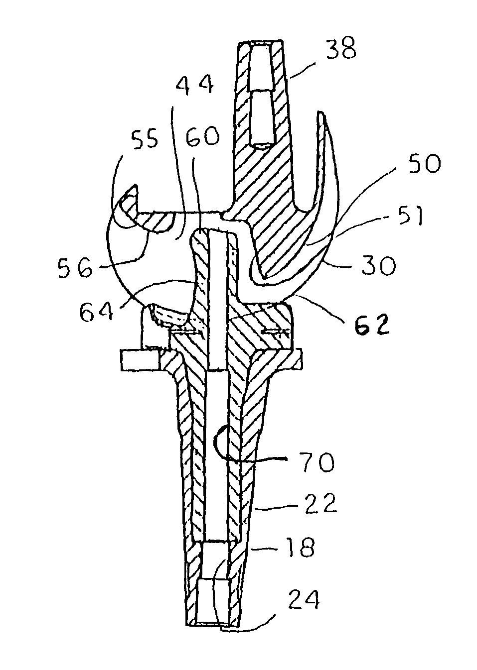
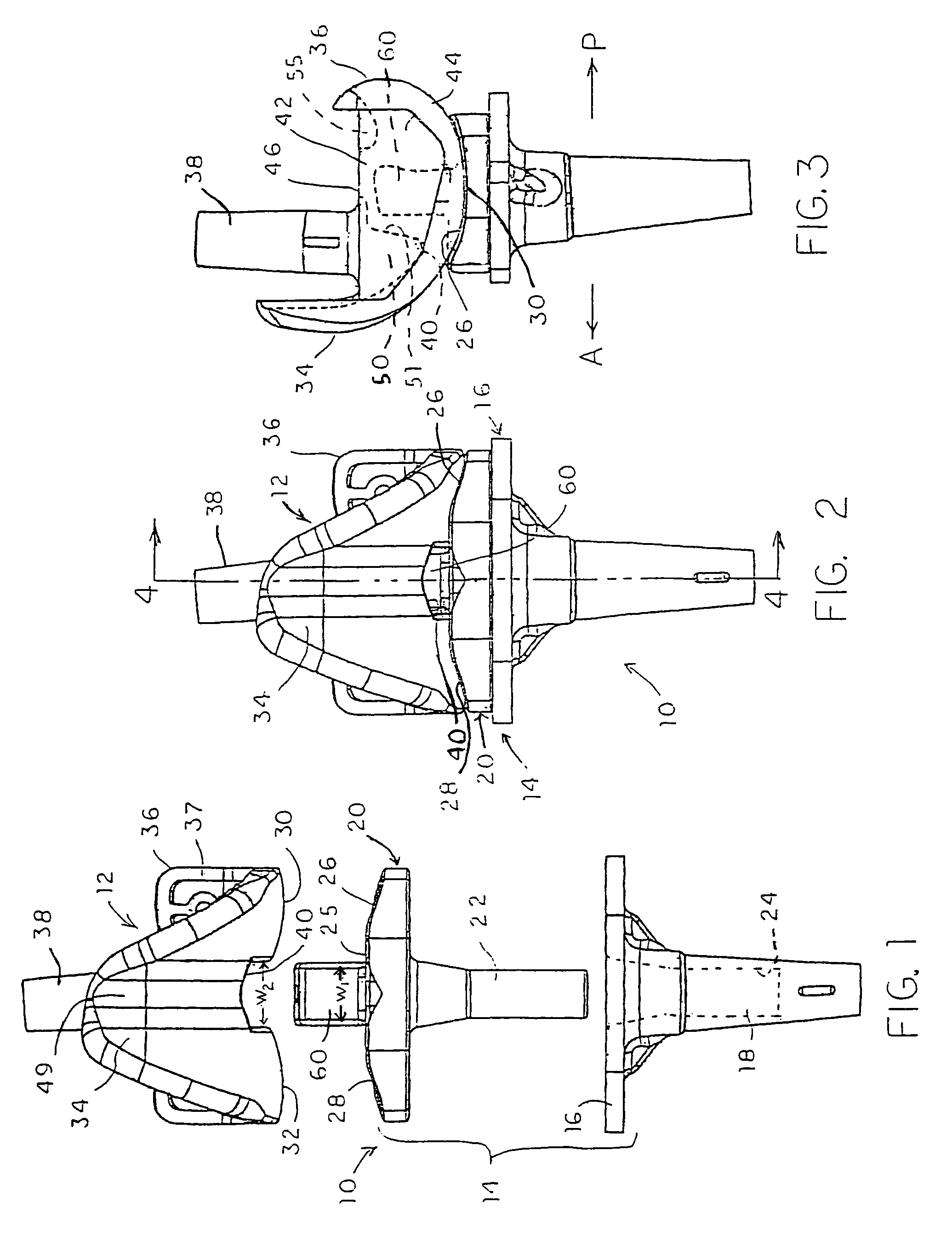
[0027]Referring to FIG. 1, a knee system 10 is depicted that includes a femoral component 12 and a tibial component 14. The tibial component includes a tibial platform 16 from which extends a tibial stem 18 that is configured for engagement within the prepared end of the tibia. A bearing 20 is rotatably mounted on the platform 16 by way of a bearing stem 22 that fits within a complementary socket 24 within the p...


PUM


Abstract

A femoral component of a knee prosthesis has spaced condyle surfaces defining a notch therebetween. The notch defines an elongated cam housing having an anterior cam and a posterior cam at opposite ends of the housing. The tibial component of the knee prosthesis includes a platform and a bearing supported on the platform, the bearing defining bearing surfaces configured to articulate with the condyle surfaces. The tibial component includes a spine projecting superiorly from the bearing that defines an anterior face and a posterior face. The posterior face and the posterior cam define complementary curved surfaces configured for cooperative engagement when the femoral component and the tibial component are at a predetermined flexion angle. The cam housing is configured to form a gap between the posterior cam and the spine when the knee is normally extended. In another feature, the spine includes a stiffening pin extending therethrough.

Description

[0001]This application is a continuation of application Ser. No. 10 / 242,122, filed on Sep. 12, 2002 now abandoned, the disclosure of which is hereby totally incorporated by reference in its entirety.BACKGROUND OF THE INVENTION[0002]The present invention relates to a knee prosthesis and more particularly to a mobile bearing knee providing posterior stabilization of the anterior-posterior translation of the femoral component relative to the tibial component.[0003]Flexion and extension of the normal human knee involves complex movements of the femur, the tibia and the patella. During flexion (i.e., when the knee is bent), the distal end of the femur and the proximal end of the tibia roll and glide relative to each other, with the center of rotation of the joint moving posteriorly over the condyles of the femur. This complex movement is typically referred to as rollback. During extension (i.e., when the leg is straightened), the tibia and femur follow a reverse path. Simultaneous with t...

Claims


Application Information

Patent Timeline
Patent Type & Authority Patents(United States)
IPC IPC(8): A61F2/38A61F2/00A61F2/30
CPCA61F2/3868A61F2/3886A61F2/3836A61F2002/30332A61F2002/30364A61F2002/30398A61F2002/30604A61F2220/0025A61F2220/0033
Inventor WYSS, JOEDIETZ, TERRYVOSLER, MARC C.RUNNING, DON
Owner DEPUY SYNTHES PROD INC
Why Eureka
Try Eureka