Fuel cell system and control method thereof

a fuel cell and control method technology, applied in the direction of electrochemical generators, secondary cell servicing/maintenance, transportation and packaging, etc., can solve the problems of increasing the power consumption of the reactant gas supply apparatus, increasing the power consumption of the heating device, and so as to promote the warming up of the fuel cell and increase the generating power of the fuel cell. , the effect of increasing the temperature of the fuel cell

Active Publication Date: 2013-02-26
NISSAN MOTOR CO LTD
View PDF13 Cites 6 Cited by
  • Summary
  • Abstract
  • Description
  • Claims
  • Application Information

AI Technical Summary

Benefits of technology

[0011]Thus, in the various embodiments of the present invention, as disclosed in detail below, the operation of the fuel cell is prevented from becoming unstable or the fuel cell is enabled to recover from an unstable power generation condition. As a result, the generating power of the fuel cell can be readily increased during a warm-up operation and the temperature of the fuel cell can be increased to promote the warming-up of the fuel cell.

Problems solved by technology

During a warm-up operation, the controller causes the reactant gas supply apparatus to start a flow of the reactant gas and to increase the flow of the reactant gas over time such that the reactant gas supply apparatus starts to consume power and consumes increased power over time.
Additionally, after the flow of the reactant gas is started, the controller causes the heating device to start heating the coolant supplied to the fuel cell such that the heating device consumes power.
The method includes starting a flow of the reactant gas such that the reactant gas supply apparatus consumes power, increasing the flow of the reactant gas over time such that the power consumed by the reactant gas supply apparatus increases over time, and after the flow of the reactant gas is started, heating the coolant supplied to the fuel cell such that the heating device consumes power.
Additionally, after the flow of the reactant gas is started, the heating means starts heating the coolant supplied to the fuel cell such that the heating means consumes power.

Method used


Image

  • Fuel cell system and control method thereof
  • Fuel cell system and control method thereof
  • Fuel cell system and control method thereof

Examples


first embodiment

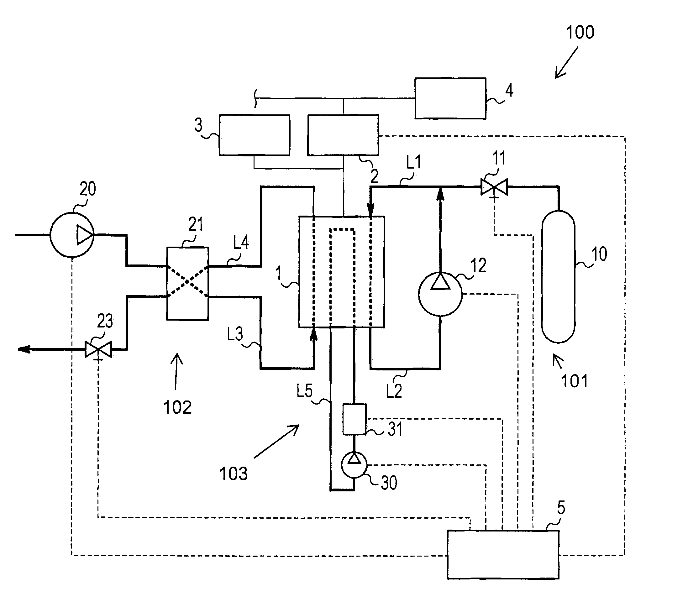
[0024]FIG. 1 is a block diagram showing a general configuration of a fuel cell system 100 according to a first embodiment of the present invention. For example, the fuel cell system 100 is mounted on a vehicle which is a movable body. The vehicle is driven by power supplied from the fuel cell system 100.

[0025]The fuel cell system 100 includes a fuel cell stack 1 having a one or more stacked fuel cell structures and separators interposed between the fuel cell structures to hold the fuel cell structures. As used herein the term fuel cell stack encompasses a fuel cell stack including one or more individual fuel cells. The structure of each fuel cell includes a fuel electrode, an oxidizer electrode, and a polymer electrolyte membrane interposed between the fuel electrode and the oxidizer electrode. In the fuel cell stack 1, fuel gas is supplied to each fuel electrode, and oxidizing gas is supplied to each oxidizer electrode. Collectively, the fuel gas and the oxidizing gas are termed “r...

second embodiment

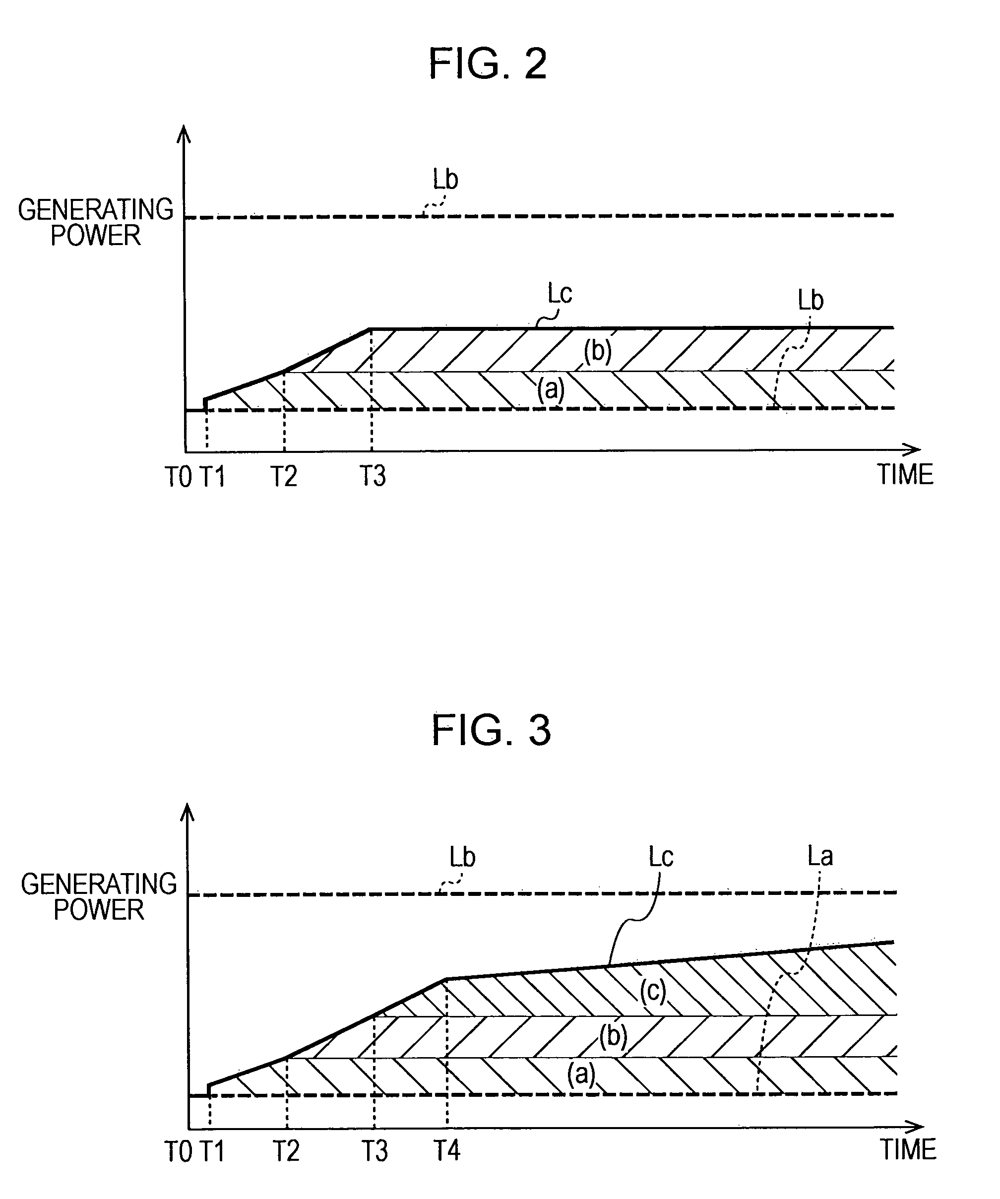
[0051]A fuel cell system according a second embodiment of the present invention is described below. FIG. 3 is a conceptual diagram showing a control method of the fuel cell system according to this embodiment. FIG. 9 is a control flowchart of this embodiment, which is different from FIG. 8 in that step S14 is added.

[0052]At time T3, as in the first embodiment, the controller 5 holds the amount of power supplied to the heater 31 constant in step S13. Then, in step S14, the controller 5 performs a third power consumption control in which the supply pressure of the air to the fuel cell stack 1 is increased relative to the warm-up pressure. The pressure of the air can be increased by increasing the rotational speed of the compressor 20 and / or by decreasing the opening of the air backpressure regulating valve 23. At this time, taking account of the power to be consumed by the compressor 20 in accordance with the increase in the rotational speed needed to increase the air pressure over ti...

third embodiment

[0058]A fuel cell system according a third embodiment of the present invention is described below. FIG. 4 is a conceptual diagram showing a control method of the fuel cell system according to this embodiment. FIG. 10 is a control flowchart of this embodiment.

[0059]The third embodiment is different from the second embodiment in that, when it is determined at time T5 that the generating power of the fuel cell stack 1 is decreasing, the controller 5 decreases the target generating power Lc correspondingly. The generating power of the fuel cell stack 1 may be decreasing because, for example, too much water is accumulating in the vicinity of the electrolyte membrane or operation of the fuel cell stack 1 has become, or is starting to become, unstable. Thus, in step S15, when it is determined that the generating power of the fuel cell stack 1 is decreasing, the controller 5 proceeds to step S16 and the power consuming equipment is stopped. Also, the controller 5 decreases a power consumpti...


PUM

PropertyMeasurementUnit
time T1aaaaaaaaaa
timeaaaaaaaaaa
timeaaaaaaaaaa

Abstract

The present invention provides a fuel cell system including a fuel cell configured to cause reactant gas to be electrochemically reacted to generate electrical power when the reactant gas is supplied to the fuel cell, power consuming equipment such as a reactant gas supply apparatus and a heating device operable to consume electrical power generated by the fuel cell, and a controller for controlling operation of the fuel cell system. During a warm-up operation, the controller causes the reactant gas supply apparatus to start a flow of the reactant gas and to increase the flow of the reactant gas over time, such that the reactant gas supply device starts to consume power and consumes increased power over time. After starting the flow of the reactant gas, the controller causes the heating device to start heating the coolant such that the heating device consumes power.

Description

CROSS-REFERENCE TO RELATED APPLICATIONS[0001]This application claims priority to Japanese Patent Application No. 2008-043207 filed Feb. 25, 2008, which is incorporated by reference herein in the entirety.BACKGROUND OF THE INVENTION[0002]1. Field of the Invention[0003]The present invention relates to a fuel cell system and a control method of the fuel cell system.[0004]2. Description of the Related Art[0005]A fuel cell system having a fuel cell has been known. In the fuel cell, fuel gas (for example, hydrogen) is supplied to a fuel electrode, and oxidizing gas (for example, air) is supplied to an oxidizer electrode. The gases are electrochemically reacted with each other to generate power. Such a fuel cell system may perform a warm-up operation in order to improve starting of the system in a cool-temperature environment.[0006]For example, Japanese Unexamined Patent Application Publication No. 2002-313388 discloses a method of decreasing power generation efficiency by decreasing a sup...

Claims


Application Information

Patent Timeline
Patent Type & Authority Patents(United States)
IPC IPC(8): H01M8/04H01M8/00H01M8/10
CPCH01M8/04037H01M8/04089H01M8/04268H01M8/04604H01M8/04626H01M8/04723H01M8/04753H01M8/04776H01M8/0494H01M8/04985H01M16/006H01M8/04104Y02E60/50H01M8/04953Y02E60/10
Inventor HASEGAWA, JUNICHI
Owner NISSAN MOTOR CO LTD
Why Eureka
Try Eureka