Deployable structures with quadrilateral reticulations

a deployment structure and quadrilateral technology, applied in the field of compactly stowable and deployable structures, can solve the problems of poor dimensional stability of the reflector class, limited surface area to the diameter of the reflector, and limited use of the lower frequency

Inactive Publication Date: 2013-02-26
THE UNITED STATES OF AMERICA AS REPRESETNED BY THE SEC OF THE AIR FORCE
View PDF6 Cites 10 Cited by
  • Summary
  • Abstract
  • Description
  • Claims
  • Application Information

AI Technical Summary

Benefits of technology

The present invention is a non-planar, segmented surface support structure for space communications and radar applications. It consists of four-sided structural loops arranged in a non-planar pattern. The loops are packaged into a compact configuration and then rotated until they are all parallel and tightly bundled. This design allows for strength and flexibility while also allowing for the replacement of the reflective surface with photovoltaic cells for creating a solar array. The technical effect of this invention is to provide a highly flexible and effective surface support system that can withstand the rigors of space and radar applications.

Problems solved by technology

The wrap-rib mesh reflector averts some of this process by relying on precisely shaped radial ribs (e.g., U.S. Pat. No. 5,446,474) however; the resulting surface is still limited to lower frequency use due to faceting between ribs.
This class of reflector suffers from poor dimensional stability due to large temperature variations and high material coefficients of thermal expansion.
Spring-back reflectors deform the reflector surface into a cylindrical shape compatible with launch vehicles; however, the longest packaged dimension is limited to the diameter of the reflector.
While each panel is dimensionally stable, relative alignment of the petals is challenging and the resulting mechanisms are heavy and do not package well.

Method used


Image

  • Deployable structures with quadrilateral reticulations
  • Deployable structures with quadrilateral reticulations
  • Deployable structures with quadrilateral reticulations

Examples


Embodiment Construction

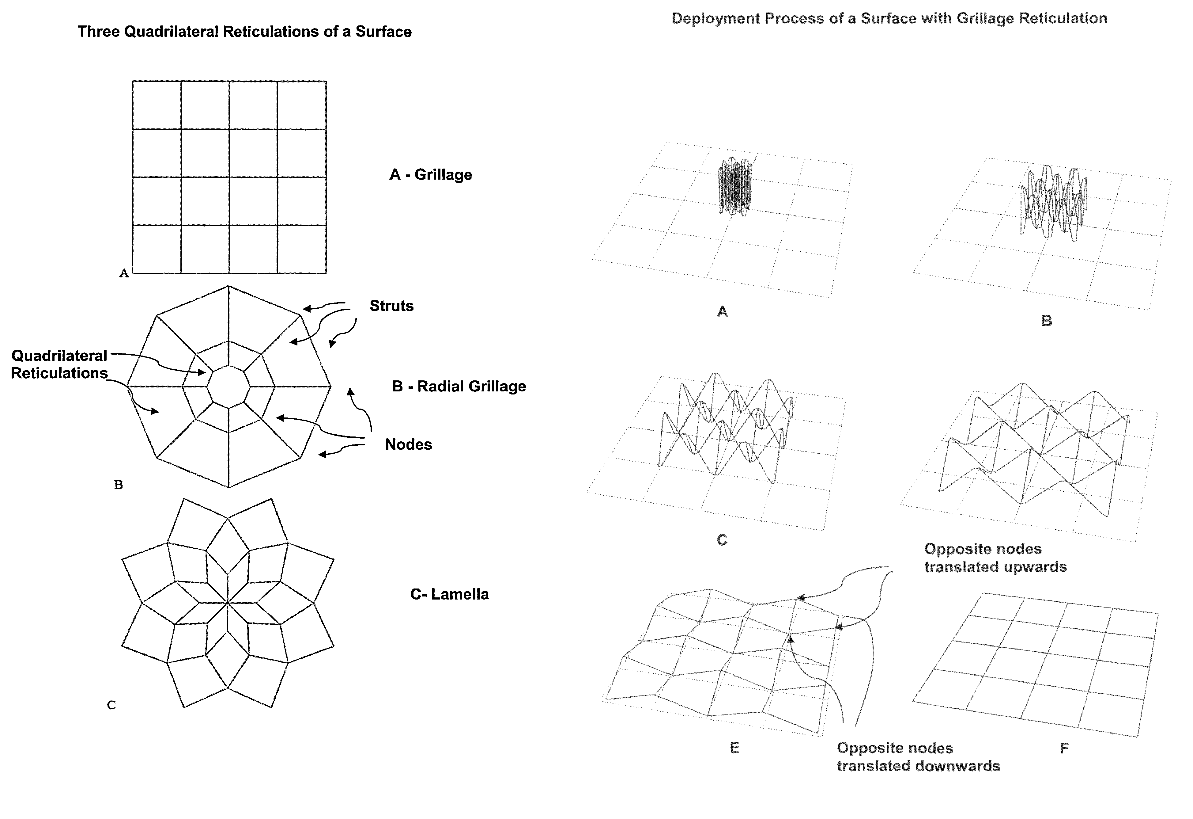
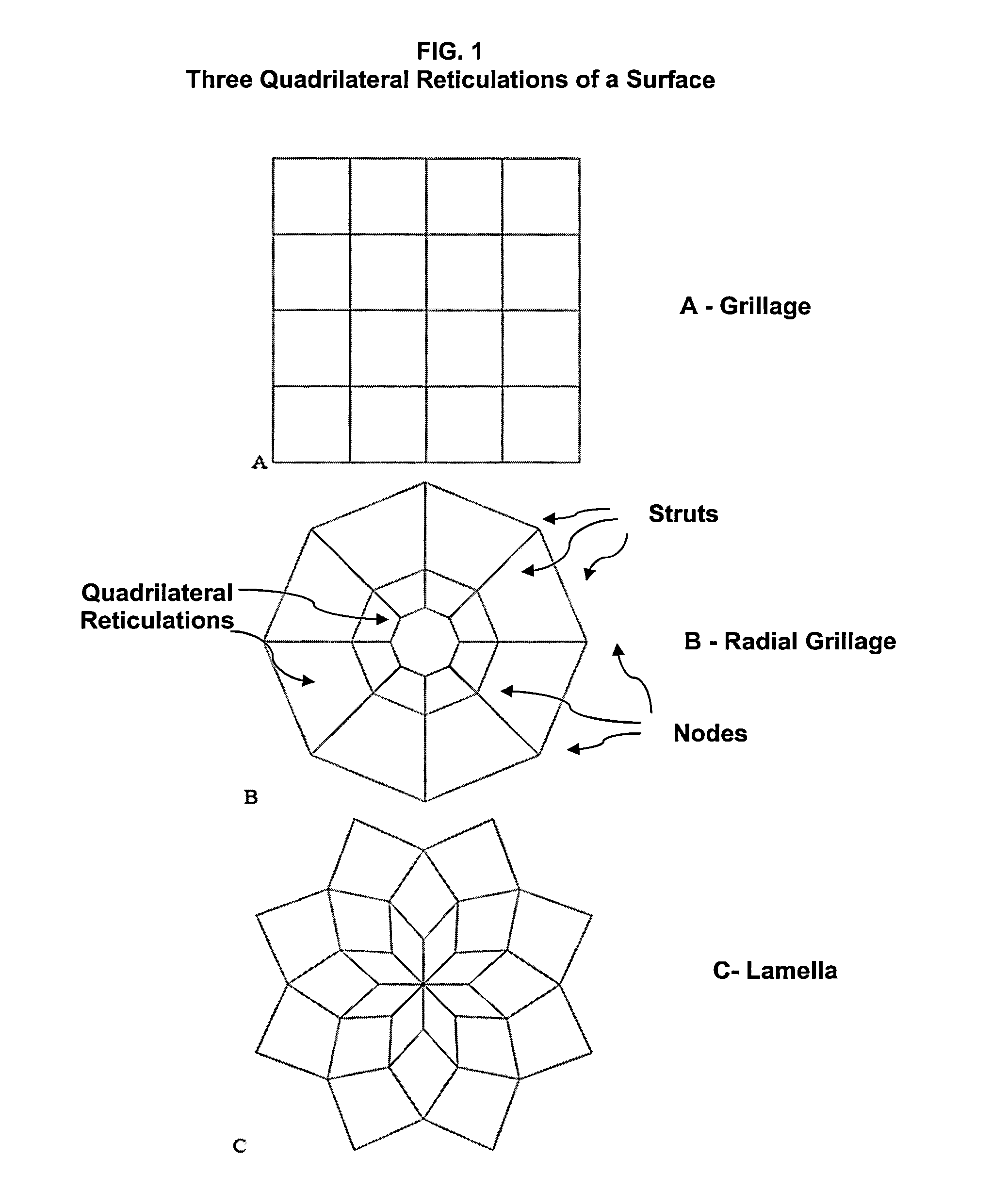
[0019]The current invention is a hybrid deformable, segmented surface support structure that is compatible with deployable thin shell reflector segments, meshed radio frequency (RF) reflective surfaces, tensioned solar array blankets, and rolled thin film photovoltaic arrays. It employs deployable structures with quadrilateral reticulations.

[0020]The structure is composed of multiple four member closed loops assembled to create an effective surface. Three quadrilateral reticulations are possible and are shown in FIG. 1: grillage, radial grillage and lamellar. These reticulations are common in civil engineering applications and various methods have been devised to render them deployable. However, nearly all prior work has been associated with pantographic (scissor) based deployable structures. A comprehensive review of the prior art associated pantographic deployable structures is found in Hanaor (Hanaor, A. and Levy, R., “Evaluation of Deployable Structures for Space Enclosures,” In...


PUM


Abstract

A non-planar surface support structure that is compatible with deployable thin shell reflector segments. The structure is composed of multiple four strut closed loops connected to compliant hinges at the nodes to create an effective surface. The deployed surface shape is determined by the strut lengths (L) and the node locations and the packaged compatibility constraint in which L1+L3−L2−L4 approximately equals zero. Each of the compliant hinges have degrees of freedom such that the compact configuration of the support structure is obtained by the translation of two opposite nodes of each loop upwards and the remaining two nodes downwards in a continuous process until all struts are approximately parallel and tightly bundled and the hinges lock out all degrees of freedom in the deployed configuration.

Description

STATEMENT OF GOVERNMENT INTEREST[0001]The conditions under which this invention was made are such as to entitle the Government of the United States under paragraph I(a) of Executive Order 10096, as represented by the Secretary of the Air Force, to the entire right, title and interest therein, including foreign rights.BACKGROUND OF THE INVENTION[0002]The present invention relates generally to compactly stowable and deployable structures and more particularly to those that are compatible with deployable thin-shell reflector segments. In the deployed configuration, the invention is well suited to collect or focus transmitted and received electromagnetic energy. The invention could be used in communication, radar, electromagnetic energy concentration and solar array systems. Reflector gain characterizes the deployed configuration in energy concentration applications and increases with increasing aperture area. The furled (packaged) configuration is engineered to minimize packaged volume...

Claims


Application Information

Patent Timeline
Patent Type & Authority Patents(United States)
IPC IPC(8): H01Q1/08H01Q15/20
CPCH01Q15/161F24J2/1057H02S30/20B64G1/44B64G1/66B64G1/222Y02E10/40F24S23/82Y02E10/50B64G1/2224
Inventor MURPHEY, THOMAS W.FOOTDALE, JOSEPH N.
Owner THE UNITED STATES OF AMERICA AS REPRESETNED BY THE SEC OF THE AIR FORCE
Why Eureka
Try Eureka