
Frame sync detecting circuit and FSK receiver using the same

a frame sync and receiver technology, applied in frequency-modulated carrier systems, amplitude demodulation, digital transmission, etc., can solve the problems of adversely affecting the establishment of synchronization, difficult to detect a specific word pattern for frame synchronization, etc., and achieve rapid establishment of frame synchronization and high degree of accuracy

Active Publication Date: 2013-02-26
ICOM INC
View PDF10 Cites 2 Cited by
  • Summary
  • Abstract
  • Description
  • Claims
  • Application Information

AI Technical Summary

Benefits of technology

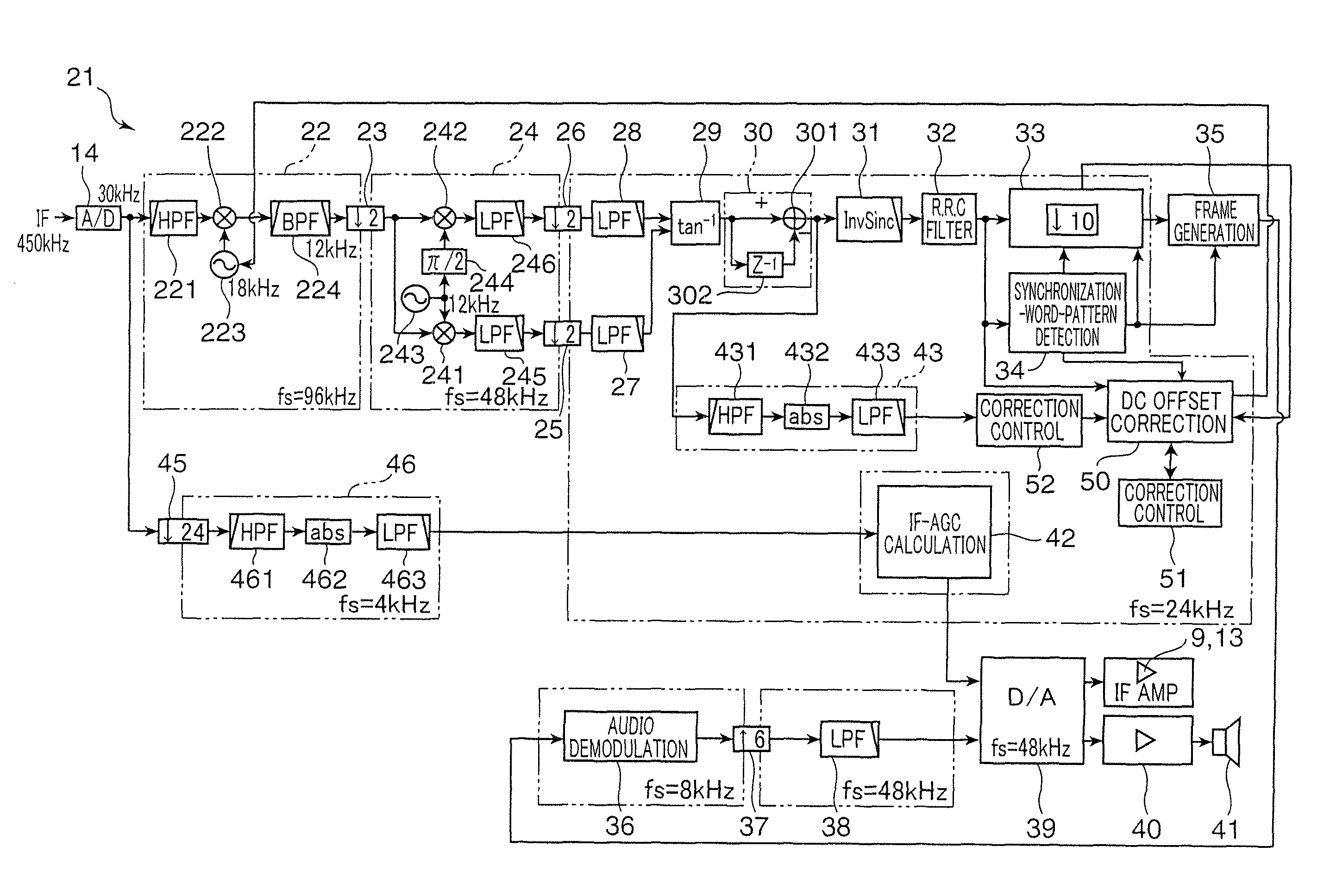
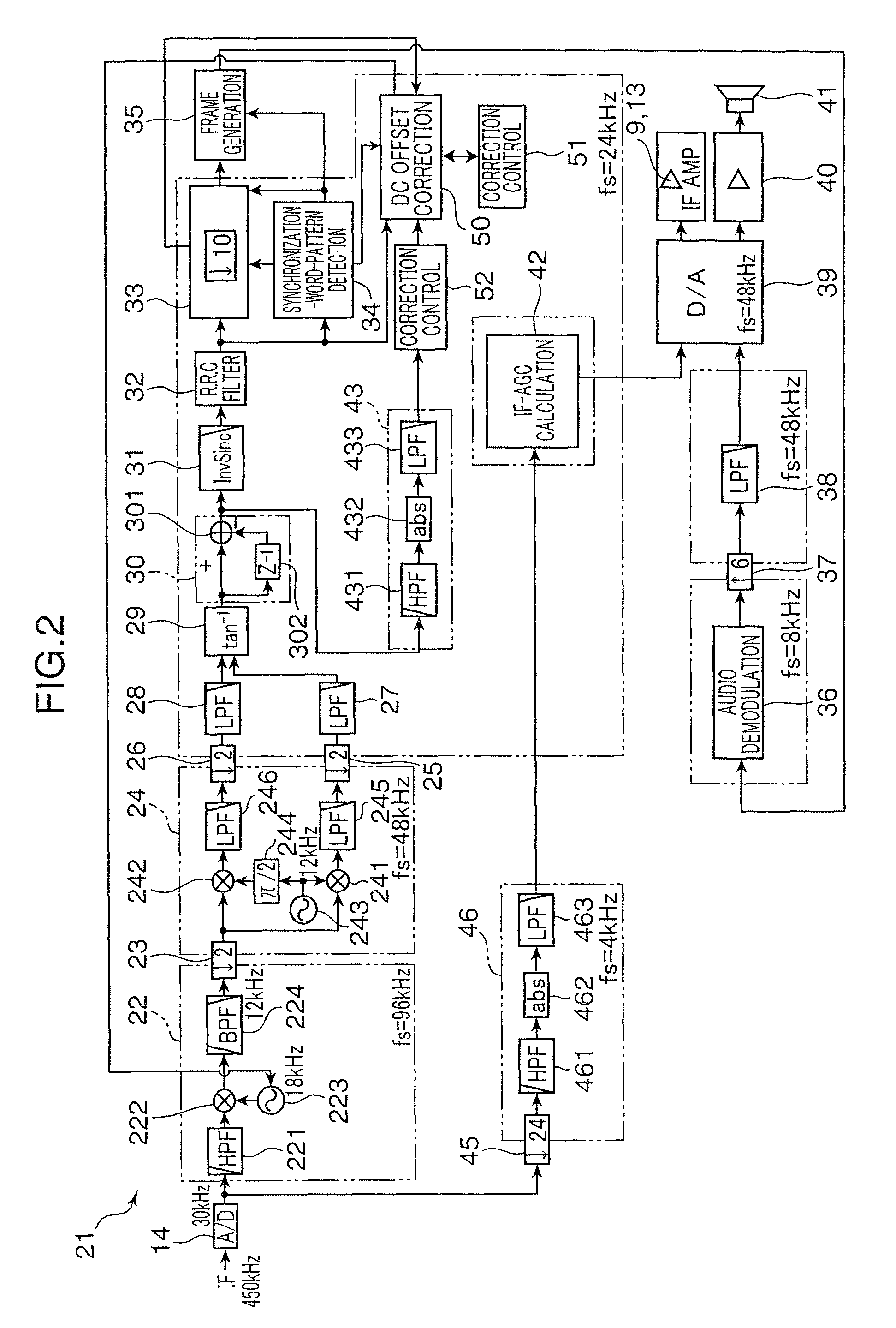
[0008]In a frame sync detecting circuit and an FSK receiver according to the present invention, a DC offset is derived from a difference between a given ideal average value and a moving average value of a given number of moving values of a received word pattern, and a DC offset correction is performed by subtracting the DC offset from respective symbol values of the received word pattern. Then, the received word pattern after the DC offset correction is compared with respective symbol values of a given sync word pattern, and, if errors in all the symbols fall within a given range, it is determined that a sync word pattern is detected. Thus, the frame sync detecting circuit and the FSK receiver according to the present invention can achieve establishment of frame synchronization rapidly and with a high degree of accuracy.

Problems solved by technology

If the DC offset is included, it will become difficult to detect a specific word pattern for frame synchronization or the like.
Consequently, noise or main data (in FSK, traffic channel) is liable to be erroneously determined as a frame sync word, which causes cases where it adversely takes longer time to establish synchronization.

Method used


Image

  • Frame sync detecting circuit and FSK receiver using the same
  • Frame sync detecting circuit and FSK receiver using the same
  • Frame sync detecting circuit and FSK receiver using the same

Examples


Embodiment Construction

[0025]One embodiment of the present invention will now be described based on the drawings. In the figures, elements or components with the same code mean that they are the same components, and duplicated description thereof will be omitted on a case-by-case basis.

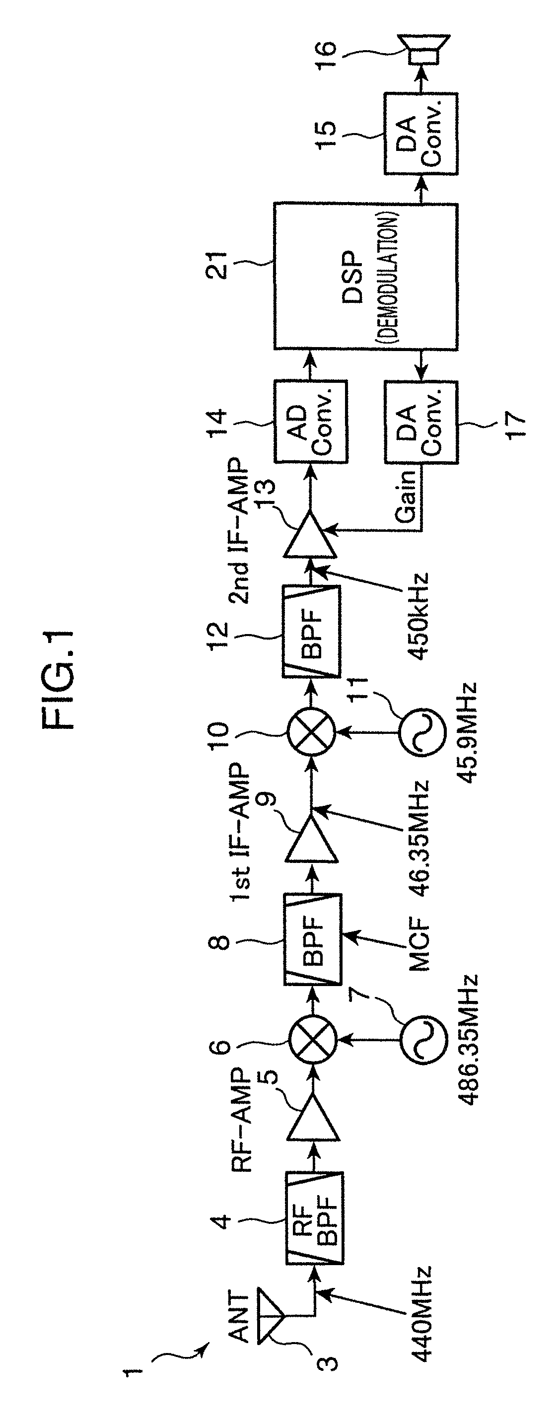
[0026]FIG. 1 is a block diagram showing an electrical configuration of an FSK receiver 1 according to one embodiment of the present invention. This FSK receiver 1 is formed using a double super heterodyne system. For example, as shown in FIG. 1, it comprises an antenna 3, a band-pass filter 4, an amplifier 5, a mixer 6, a local oscillator circuit 7, a band-pass filter 8, an amplifier 9, a mixer 10, a local oscillator circuit 11, a band-pass filter 12, an amplifier (intermediate frequency amplifier) 13, an analog / digital converter 14, a digital / analog converter 15, a speaker 16, a digital / analog converter 17, and a demodulator circuit 21.

[0027]In the FSK receiver 1, a signal is received by the antenna 3, and an FSK high-freq...


PUM


Abstract

A frame sync detecting circuit and FSK receiver sequentially derive a moving average value (□) from oversample values of a received word pattern, for given symbol periods, and a difference between the moving average value and an average value for the given symbol periods in a given sync word pattern is determined as DC offsets Δf. Subsequently, the DC offset Δf is subtracted from the received word pattern, and correlation processing with respect to the sync word pattern is performed to determine a correlation value (●). If the correlation value exceeds a predetermined threshold, it is determined that a sync word candidate has been received, and symbol values of the received word pattern after the DC offset correction are compared with respective symbol values of the sync word pattern. A sync word pattern detection is determined if errors in the symbols are within a given range.

Description

BACKGROUND OF THE INVENTION[0001]1. Field of the Invention[0002]The present invention relates to a frame sync detecting circuit which is suitably implemented in an FSK demodulator circuit or the like, and an FSK receiver using the same.[0003]2. Description of the Related Art[0004]In the FSK (Frequency Shift Keying) modulation scheme, demodulation is performed by frequency-voltage conversion. In this demodulation, voltages having levels corresponding to a plurality of (e.g., two or four) frequencies are output as a demodulated signal, and a DC offset is superimposed on the demodulated signal in connection with an error between transmitted and received frequencies. While, in a phase modulation scheme, demodulation is performed by phase-voltage conversion, and a DC offset also occurs in connection with an error between transmitted and received phases, the following description will be made based on only the FSK modulation scheme. If the DC offset is included, it will become difficult t...

Claims


Application Information

Patent Timeline
Patent Type & Authority Patents(United States)
IPC IPC(8): H04L7/00H04L27/14
CPCH04L7/042H04L27/14
Inventor SHIBATA, KAZUNORI
Owner ICOM INC
Learn More