
Method and processing installation for devolatilizing polymer melts

a technology of devolatilizing polymer melt and processing installation, which is applied in the direction of mixing/kneading with horizontally mounted tools, manufacturing tools, food shaping, etc., can solve the problems of low material throughput in this extrusion installation, low devolatilization performance, and low material throughput compared to the necessary technical effort, and achieve high devolatilization performance. , the effect of high polymer throughpu

Inactive Publication Date: 2013-03-05
COPERION
View PDF31 Cites 5 Cited by
  • Summary
  • Abstract
  • Description
  • Claims
  • Application Information

AI Technical Summary

Benefits of technology

[0007]It is the object of the invention to provide a method for devolatilizing polymer melts which ensures a high devolatilization performance and a high polymer throughput at the same time.

Problems solved by technology

The drawback of this processing installation is that the devolatilization performance, in other words the amount of the devolatilized proportion of undesirable volatile components, is low.
The drawback is that the material throughput in this extrusion installation is low compared to the necessary technical effort.

Method used


Image

  • Method and processing installation for devolatilizing polymer melts
  • Method and processing installation for devolatilizing polymer melts
  • Method and processing installation for devolatilizing polymer melts

Examples


Embodiment Construction

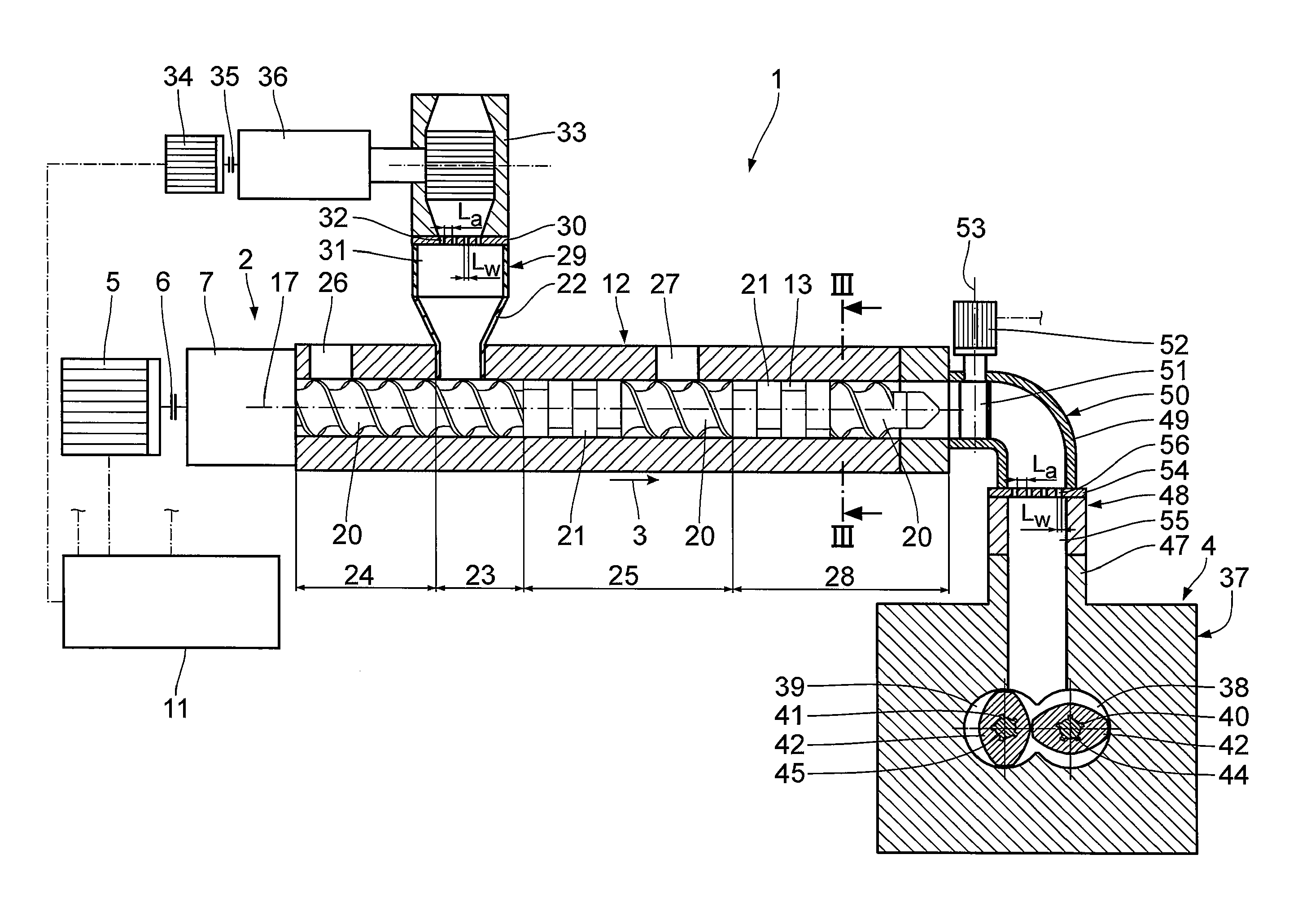
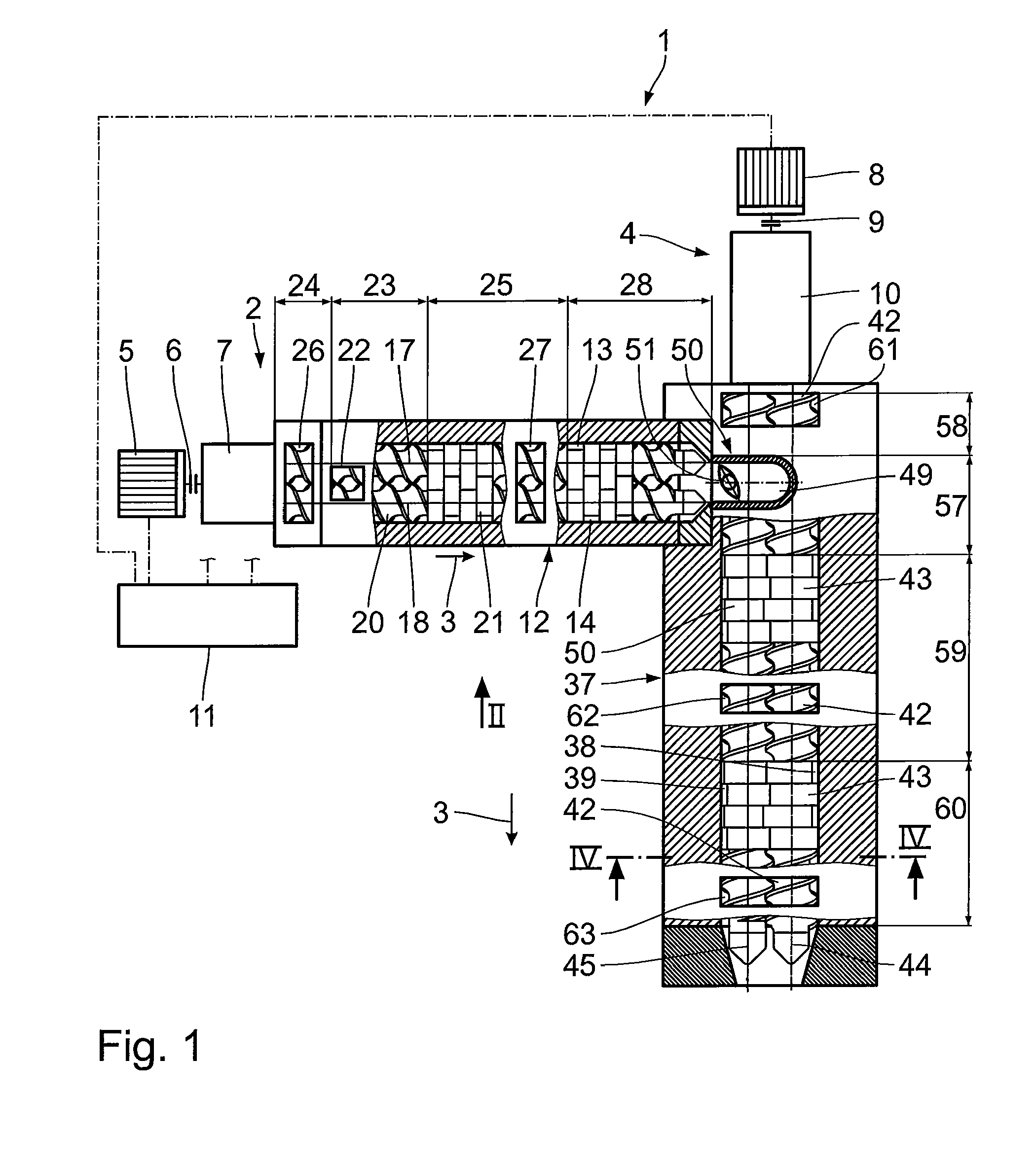
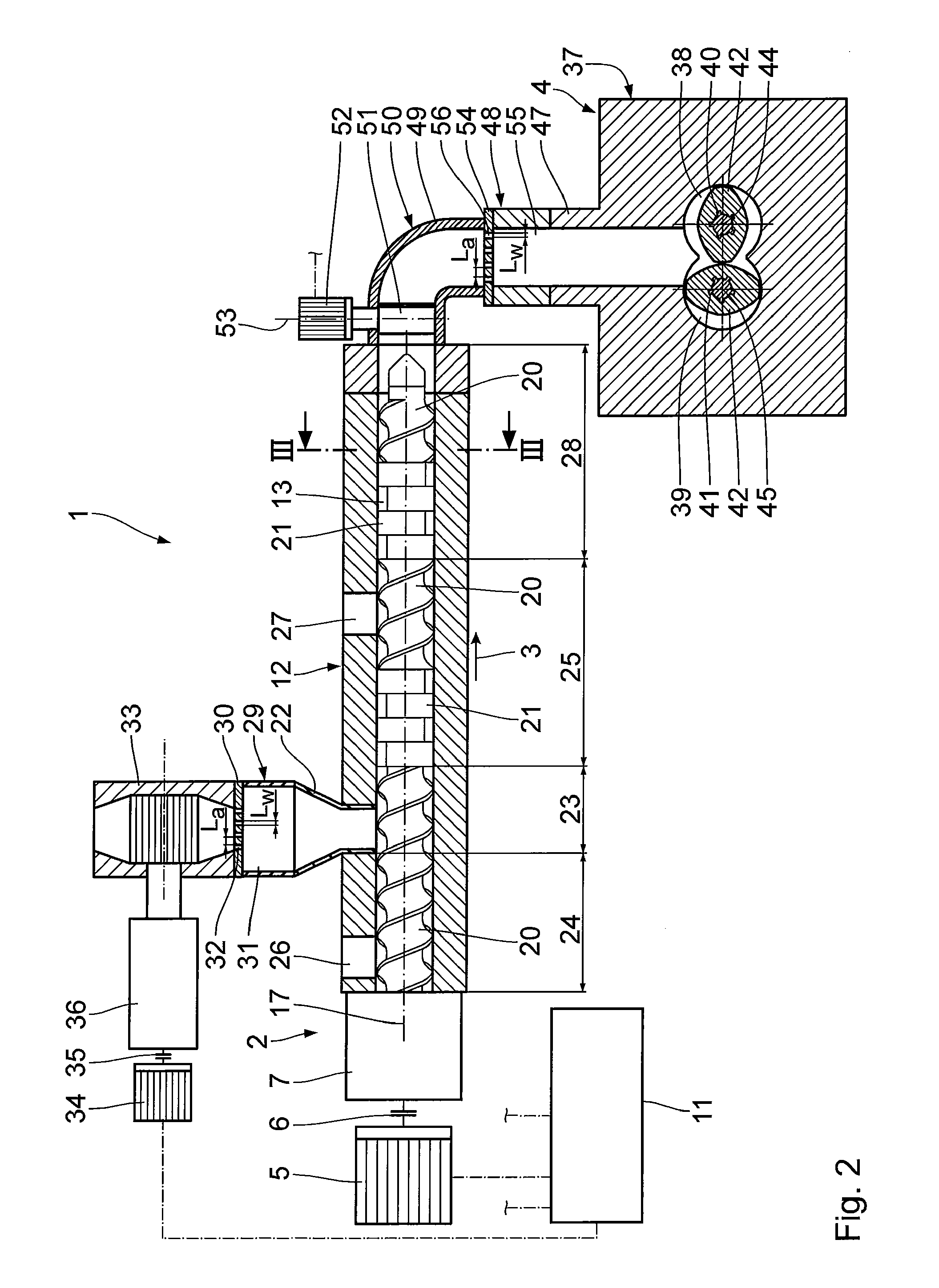
[0028]The following is a description of a first embodiment of the invention with reference to FIGS. 1 to 4. A processing installation 1 comprises a first extruder 2 and a second extruder 4 arranged downstream in a direction of conveyance 3. The first extruder 2 is arranged above the second extruder 4. The first extruder 2 is driven by means of a first drive motor 5 via a first clutch 6 and a first gear 7. Correspondingly, the second extruder 4 is driven by means of a second drive motor 8 via a second clutch 9 and a second gear 10. The drive motors 5 and 8 are controlled via a control unit 11.

[0029]The first extruder 2 comprises a casing 12 in which two first casing bores 13, 14 are formed which are parallel to each other and intermesh with each other in the manner of a lying figure eight. In these casing bores 13, 14, two first shafts 15, 16 are arranged which are coupled to the first gear 7. The first shafts 15, 16 are driven equidirectionally, in other words in the same direction ...


PUM

PropertyMeasurementUnit
perforation distance Laaaaaaaaaaa
perforation width LWaaaaaaaaaa
da/Daaaaaaaaaaa

Abstract

A processing installation for devolatilization of polymer melts comprises a first extruder and a second extruder arranged downstream thereof in a direction of conveyance. The first extruder comprises several rotatably drivable first shafts which are provided with first treatment members and several devolatilization zones with associated devolatilization ports. Correspondingly, the second extruder comprises several rotatably drivable second shafts which are provided with second treatment members and several second devolatilization zones with associated devolatilization ports. The first treatment members have an external diameter which is smaller than or equal to that of the second treatment members. A devolatilization unit is arranged in a transfer zone which interconnects the extruders. The devolatilization unit comprises a perforated plate and a clearance arranged downstream in the direction of conveyance. A control unit is configured in such a way that when the processing installation is operated, the speed of the second shafts is lower than the speed of the first shafts. The processing installation allows a high devolatilization performance and a high polymer throughput to be achieved at the same time. A throttle is arranged in the transfer zone upstream of the devolatilization unit when seen in the direction of conveyance, with the position of the throttle being adjustable by means of the control unit.

Description

BACKGROUND OF THE INVENTION[0001]1. Field of the Invention[0002]The invention relates to a method and a processing installation for devolatilizing polymer melts.[0003]2. Background Art[0004]Devolatilizing of polymer melts for improving the polymer quality is a common procedure in the industrial production of plastic materials. In this process, volatile components such as monomers, oligomers, additives required for polymerization as well as undesirable by-products impairing the quality of the polymer are devolatilized. Typical additives are for example solvents or suspending agents. The process of devolatilization allows in particular the optical and mechanical properties to be improved.[0005]US 2006 / 0245294 A1 discloses a processing installation and a method for devolatilizing bimodal polyolefins. In the processing installation, two twin-shaft extruders which rotate in the same direction are arranged one behind the other, with the second extruder, seen in the direction of conveyance...

Claims


Application Information

Patent Timeline
Patent Type & Authority Patents(United States)
IPC IPC(8): B29B7/46B29C47/50B29C48/07B29C48/255B29C48/37B29C48/38B29C48/385B29C48/40B29C48/405B29C48/54B29C48/57B29C48/76B29C48/92
CPCB29C47/0019B29C47/364B29C47/50B29C47/763B29C47/766B29C47/767B29C47/92B29C47/366B29C47/6031B29C47/6056B29C47/38B29C47/402B29C2947/92095B29C2947/92161B29C2947/92228B29C2947/9238B29C2947/9239B29C2947/9259B29C2947/92885B29C2947/92952B29C47/367B29B7/487B29B7/60B29B7/7485B29B7/84B29C48/92B29C48/07B29C48/255B29C48/37B29C48/385B29C48/387B29C48/402B29C48/38B29C48/54B29C48/57B29C48/763B29C48/766B29C48/767B29C2948/92095B29C2948/92161B29C2948/92228B29C2948/9238B29C2948/9239B29C2948/9259B29C2948/92885B29C2948/92952B29C48/405B29C48/40B29B7/483
Inventor LECHNER, FRANKCONRAD, ULRICH
Owner COPERION
Learn More