Method for controlling a hybrid drive train of a vehicle

a hybrid drivetrain and drivetrain technology, applied in mechanical equipment, propulsion parts, transportation and packaging, etc., can solve the problems of reduced driving comfort, limited control method, and electric machine may no longer be able to deliver sufficient power, so as to reduce the dynamic load of electric machine and improve driving comfor

Inactive Publication Date: 2013-03-05
ZF FRIEDRICHSHAFEN AG
View PDF9 Cites 14 Cited by
  • Summary
  • Abstract
  • Description
  • Claims
  • Application Information

AI Technical Summary

Benefits of technology

[0010]Accordingly, the purpose of the present invention is to propose an improved method for controlling a hybrid drive-train of a motor vehicle, of the type mentioned at the start, with which drag-starting of the internal combustion engine in combination with a downshift takes place with greater driving comfort and reduced dynamic loading of the powershift transmission compared with the control method according to DE 10 2006 031 684 A1.
[0020]The control method according to the invention therefore differs from the known control method according to DE 10 2006 031 684 A1 essentially in that after the internal combustion engine has been self-started the separator clutch is disengaged again, and the two drive aggregates are adjusted to the synchronous speed of the target gear separately, i.e. largely uncoupled from one another and each by independent control action. In this way the torque and speed surges that occur as the internal combustion engine is speeding up are largely completely kept apart from the electric machine and the powershift transmission, which results in greater driving comfort and lower dynamic loading of the electric machine and the powershift transmission.
[0022]In addition, improved decoupling between the internal combustion engine, the electric machine and the powershift transmission can be achieved if, from below the slipping limit at the frictional shifting element to be disengaged, the electric machine is first adjusted to an intermediate rotational speed between the synchronous speed of the currently engaged gear and the synchronous speed of the target gear and kept at that speed, and is only readjusted to the synchronous speed of the target gear when the internal combustion engine has reached or exceeded the synchronous speed of the target gear.

Problems solved by technology

The electric machine may be no longer capable of delivering sufficient power because of a predetermined maximum electric machine torque determined by its design and / or because there is no longer sufficient charge in the electrical energy accumulator.
However, this control method can only be used to a limited extent because in order to drag-start the internal combustion engine, there has to be a sufficient rotational speed difference between the input side and the output side of the separator clutch.
However, since during the dragging and speeding up of the internal combustion engine the separator clutch is engaged progressively, the torque and speed surges coming from the internal combustion engine and the control processes of the separator clutch are increasingly transmitted to the rotor of the electric machine and from there, at least in part via the frictional shifting element to be disengaged, passed on to the powershift transmission, whereby driving comfort is reduced and the wear of gearteeth and bearings in the powershift transmission is increased.

Method used


Image

  • Method for controlling a hybrid drive train of a vehicle
  • Method for controlling a hybrid drive train of a vehicle
  • Method for controlling a hybrid drive train of a vehicle

Examples


Embodiment Construction

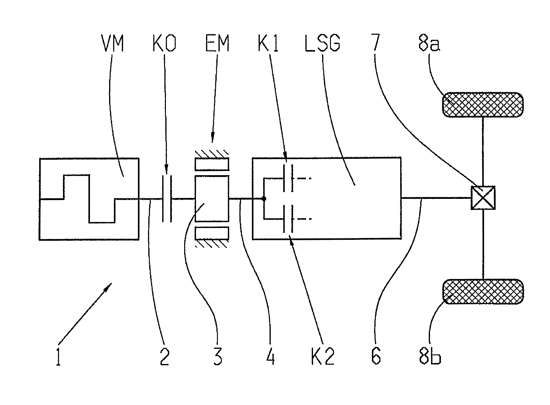
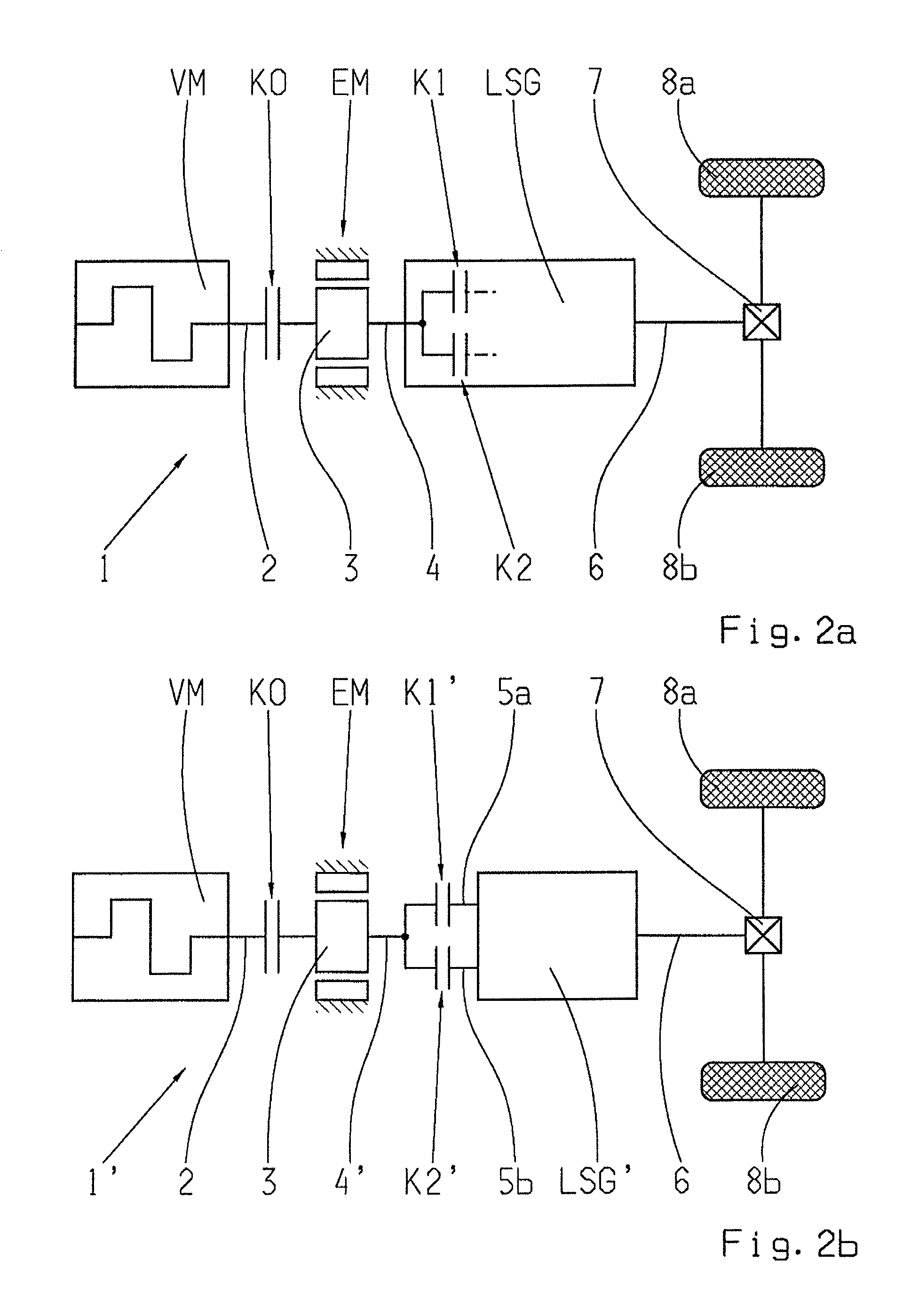
[0031]FIG. 2a and FIG. 2b show schematic representations, in each case of a parallel-action hybrid drive-train 1, 1′ in which the control method according to the invention can be used. Both versions of the hybrid drive-train 1, 1′ comprise an internal combustion engine VM with a driveshaft 2, an electric machine EM that can be operated at least as a motor and which has a rotor 3, and a powershift transmission LSG or LSG′ respectively. In each case the rotor 3 of the electric machine EM can be connected on the input side by means of an automated separator clutch K0 to the driveshaft 2 of the internal combustion engine VM and also separated therefrom, so that when necessary the internal combustion engine can be started by the electric machine EM by being coupled to it and then decoupled from it. On the output side the rotor 3 of the electric machine EM is in each case connected to an input element 4, 4′ of the powershift transmission LSG or LSG′.

[0032]In the embodiment of the hybrid d...


PUM


Abstract

A method of controlling a hybrid drive-train of a vehicle in which the hybrid drive-train comprises a combustion engine having a driveshaft, an electric machine that can be connected to the driveshaft of the engine by a clutch, an automated transmission with an input which is connected to the rotor of the electric machine, and shifting elements for shifting between two gears. During electric driving operation with the engine stopped and the clutch disengaged, the engine can be drag-started in combination with a downshift in the transmission. Drag starting of the engine is carried out by disengaging the frictional shifting element to be disengaged to below a slipping limit, engaging the clutch until the engine reaches or exceeds its minimum starting speed, starting the engine self-starts, substantially disengaging the clutch, separately adjusting the engine and electric machine to the synchronous speed of the target gear, and fully engaging and disengaging associated shifting elements.

Description

[0001]This application claims priority from German patent application serial no. 10 2010 043 355.1 filed Nov. 4, 2010.FIELD OF THE INVENTION[0002]The invention concerns a method for controlling a hybrid drive-train of a motor vehicle, which comprises an internal combustion engine with a driveshaft, an electric machine that can be operated at least as a motor with a rotor that can be connected to the driveshaft of the internal combustion engine by means of a semi-automatic separator clutch, a semi-automatic powershift transmission having an input element which is in drive connection with the rotor of the electric machine, and with at least two frictional shifting elements for time-overlapped shifting between two gears, such that during electric driving operation with the internal combustion engine stopped and the separator clutch disengaged, the internal combustion engine is drag-started in combination with a downshift of the powershift transmission.BACKGROUND OF THE INVENTION[0003]A...

Claims


Application Information

Patent Timeline
Patent Type & Authority Patents(United States)
IPC IPC(8): B60W10/02B60W10/08
CPCB60K6/48B60W10/02B60W10/06B60W10/08B60W10/113B60W20/00B60W30/192Y10T477/669B60Y2300/49F16H2061/0422Y02T10/6221Y02T10/6286Y10T477/26Y02T10/62B60W20/40B60W2710/021
Inventor SCHIELE, PETERSTEINHAUSER, KLAUSALLGAIER, BERND
Owner ZF FRIEDRICHSHAFEN AG
Why Eureka
Try Eureka