Sensing device, display device, electronic apparatus, and sensing method

a display device and sensing technology, applied in the field of sensing devices, display devices, electronic devices, and sensing methods, can solve the problems of increasing power consumption in proportion to the shortened detection period, inability to trace the high-speed movement of a finger or light pen, and inability to smoothly input handwritten images or the like by touch input, so as to achieve smooth touch input and reduce power consumption

Inactive Publication Date: 2013-03-05
JAPAN DISPLAY WEST
View PDF19 Cites 28 Cited by
  • Summary
  • Abstract
  • Description
  • Claims
  • Application Information

AI Technical Summary

Benefits of technology

[0006]An advantage of some aspects of the invention is to make it possible to smoothly perform touch input while reducing the power consumption.

Problems solved by technology

Accordingly, for example, when a detection period of the coordinate position is 60 Hz, it is not possible to trace the high-speed movement of a finger or light pen.
This makes it difficult to smoothly input a handwritten image or the like by touch input.
In this case, however, the power consumption increases in proportion to the shortened detection period.
As a result, the excessive power consumption occurs.
For this reason, when the surrounding area of the sensing device is dark, it is difficult to sense the approach when the brightness of light emitted from the backlight is weak.
As a result, the excessive power consumption occurs.

Method used


Image

  • Sensing device, display device, electronic apparatus, and sensing method
  • Sensing device, display device, electronic apparatus, and sensing method
  • Sensing device, display device, electronic apparatus, and sensing method

Examples


embodiment a1

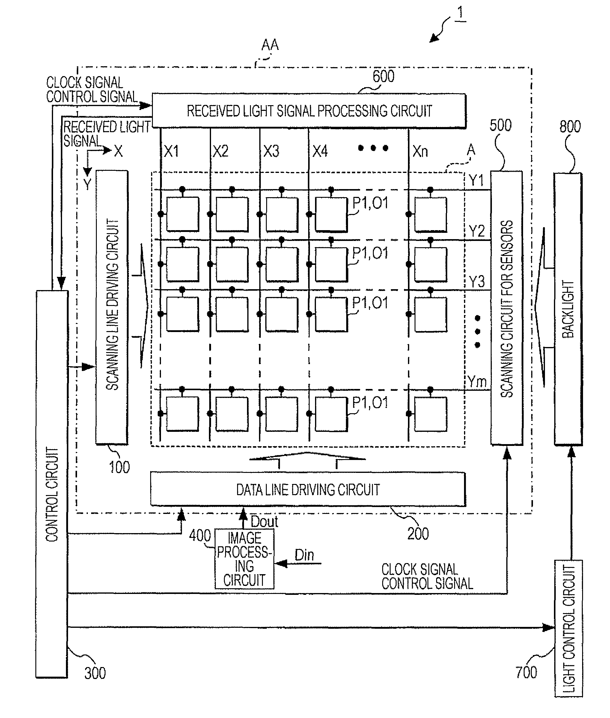
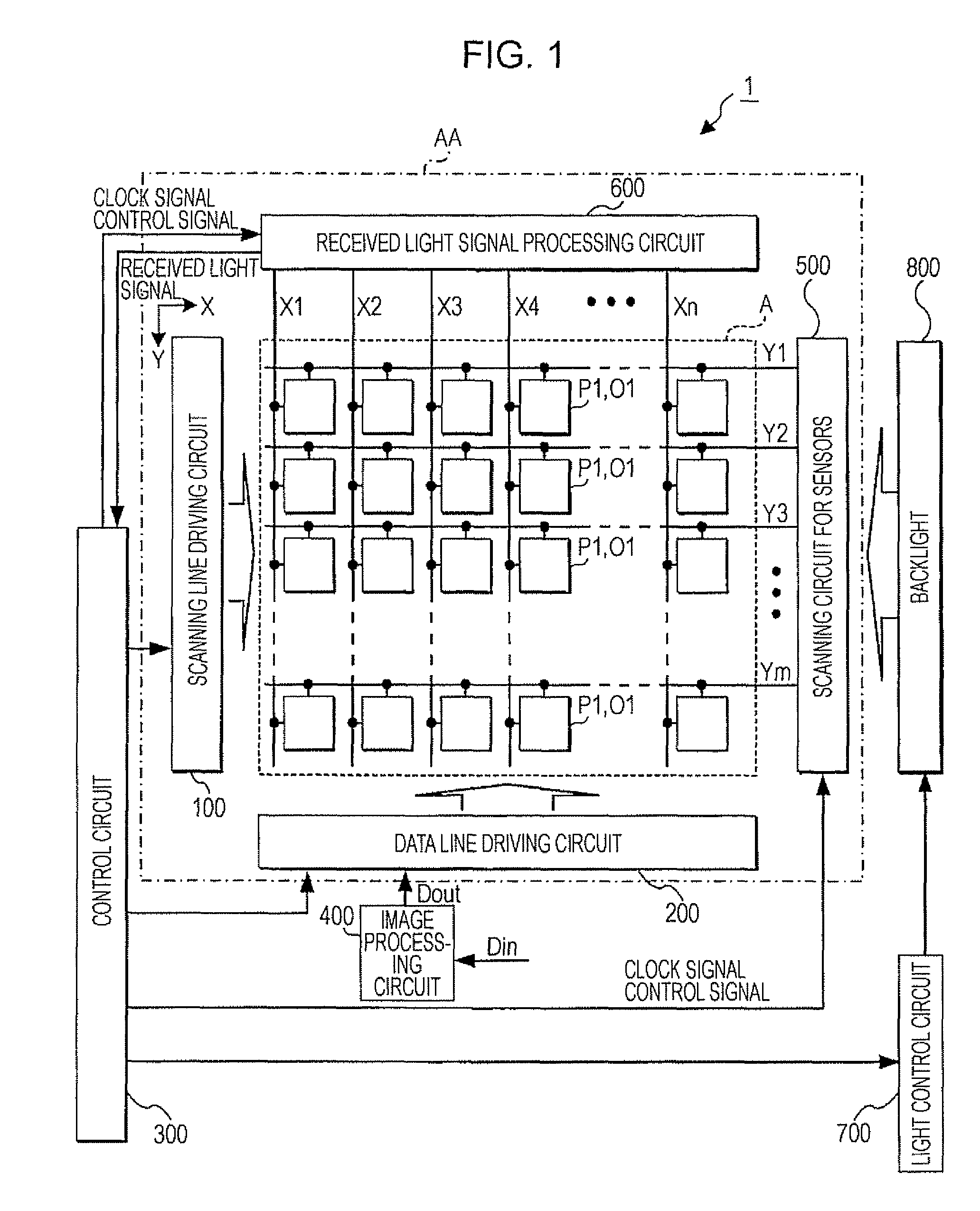
[0097]FIG. 1 is a block diagram illustrating the configuration of a liquid crystal display device 1 according to the embodiment A1.

[0098]As shown in FIG. 1, the liquid crystal display device 1 includes a liquid crystal panel AA, a control circuit 300, an image processing circuit 400, a light control circuit 700, and a backlight 800. The liquid crystal panel AA is obtained by bonding an element substrate, in which a thin film transistor as a switching element is formed, and a counter substrate together in a state where electrode formed surfaces of the substrates face each other and a predetermined gap is maintained between the substrates. Liquid crystal is interposed in the gap. In addition, the liquid crystal panel AA includes an image display area A, a scanning line driving circuit 100, a data line driving circuit 200, a scanning circuit 500 for sensors, and a received light signal processing circuit 600 which are provided on the element substrate. In the image display area A, ‘m (...

embodiment b1

[0142]Next, an embodiment B1 will be described.

[0143]In addition, since the hardware configuration of a liquid crystal display according to the present embodiment is almost similar to that of the liquid crystal display device 1 according to the embodiment A1, the same reference numerals as in the embodiment A1 are used. In addition, an explanation on the same parts as in the embodiment A1 will be omitted.

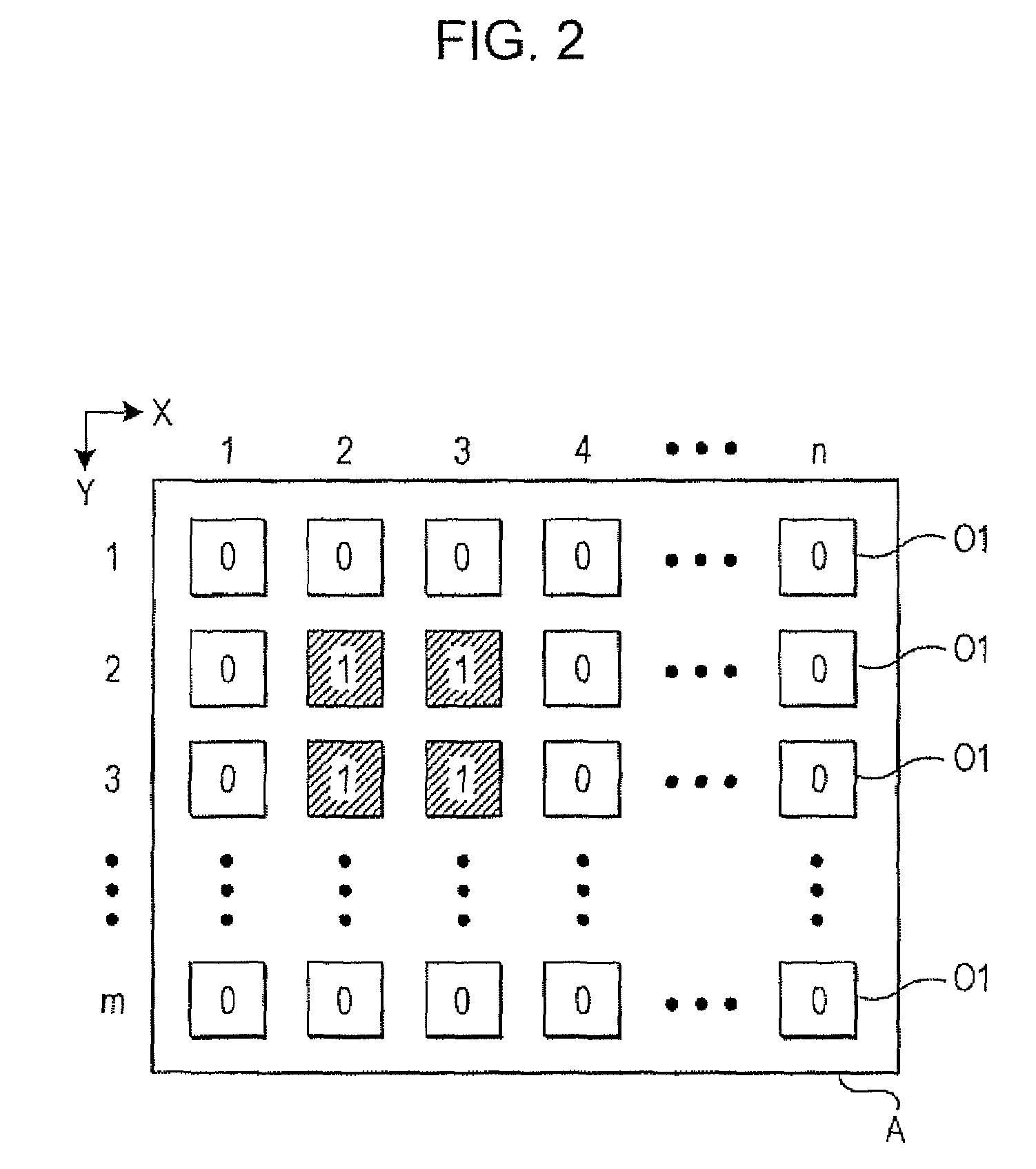
[0144]The liquid crystal display device 1 according to the present embodiment can determine whether or not there is a touch on the basis of received light signals for one screen and determine whether or not the finger or the touch pen 50 approaches close to the display screen (whether or not there is approach). In addition, the distance allowing it to be determined whether or not there is approach is a distance within which reflected light or shadow of a finger or the touch pen 50 can be sensed from the received light amount of each photodetection circuit O1.

[0145]Specifically, firs...

embodiment b2

[0178]In the embodiment B1, the case where the received light signals for one screen are read every 60 Hz in the normal mode and every 10 Hz in the low consumption mode has been described. In the present embodiment, a case where received light signals are read from only some photodetection circuits O1 provided in the image display area A in the low consumption mode will be described.

[0179]The liquid crystal display device 1 according to the present embodiment has a normal mode and a low consumption mode, similar to the case of the embodiment B1. In the normal mode, the scanning circuit 500 for sensors and the received light signal processing circuit 600 read received light signals every 60 Hz from all photodetection circuits O1 provided in the image display area A. On the other hand, in the low consumption mode, the scanning circuit 500 for sensors and the received light signal processing circuit 600 read the received light signals every 10 Hz from some of the photodetection circuit...


PUM


Abstract

A sensing device includes: a plurality of sensors that are arrayed on a screen and that generate first detection signals each having a level corresponding to a touch state of an object on the screen or a distance between the object and the screen; a read unit that reads the first detection signals from the plurality of sensors at predetermined periods; a binarization unit that compares a level of each of the first detection signals read by the read unit with a threshold value and generates a second detection signal that is binarized; a determination unit that determines whether or not the object touches the screen on the basis of each second detection signal; a detection unit that detects a touch position of the object on the screen on the basis of each second detection signal; and a control unit that controls the read unit such that the predetermined period becomes a first period when the determination unit determines that there is no touch and that controls the read unit such that the predetermined period becomes a second period shorter than the first period when the determination unit determines that there is a touch.

Description

BACKGROUND[0001]1. Technical Field[0002]The present invention relates to a technique of detecting the touch position of an object, such as a finger or a pen, on a screen.[0003]2. Related Art[0004]A liquid crystal display device that detects the coordinate position on a screen designated by a finger or a light pen is disclosed in JP-A-2004-318819. The liquid crystal display device includes an image reading sensor 33, which images incident light, for every pixel and detects the coordinate position from a change of imaging data when the finger or the light pen approaches or touches the screen. In addition, in the liquid crystal display device, the imaging data is not read from all image reading sensors 33 arrayed in a pixel array section 1, but is read for every four rows in the row direction and for every three columns in the column direction.[0005]In the liquid crystal display device disclosed in JP-A-2004-318819, the coordinate position designated by the finger or the light pen is a...

Claims


Application Information

Patent Timeline
Patent Type & Authority Patents(United States)
IPC IPC(8): G06F3/041
CPCG06F3/0416G06F3/042G06F1/3262G06F3/0354G06F3/0412G06F3/0487G06F3/04166
Inventor CHINO, TAKETO
Owner JAPAN DISPLAY WEST
Why Eureka
Try Eureka