Systems and methods for overlaid switching networks

a switching network and system technology, applied in the field of communication switching networks, can solve the problems of failure to compensate for any potential failure of a switching element, failure to achieve redundancy and fault tolerance, and omission of connections depicted by dotted lines, so as to reduce the distance of the average connection and reduce the average latency between two external ports

Inactive Publication Date: 2013-03-05
LU HAW MINN +1
View PDF25 Cites 10 Cited by
  • Summary
  • Abstract
  • Description
  • Claims
  • Application Information

AI Technical Summary

Benefits of technology

[0013]The redundant blocking compensated cyclic group (RBCCG) networks and hybrids form the basic building blocks of more elaborate switching networks. One such class of networks are those formed from the Cartesian product of two switching networks. The Cartesian product of two switching networks can reduce the distance of the average connection between stages as compared to a similarly equipped “flat” switching network.
[0014]Another class of networks that can be formed from the basic building block networks is the overlaid network where two or more network topologies are overlaid to form an elaborate multidirectional network. In such an overlaid network the average latency between two external ports can be reduced.

Problems solved by technology

These traditional radix networks offer functional connectivity, but lack redundancy and fault tolerance.
In either case, the resultant network does increase the ability to tolerate a failure in an internal connection, but fails to compensate for any potential failure in a switching element.
Often in this technique, the connections depicted by the dotted lines are often considered overly redundant and are omitted.

Method used


Image

  • Systems and methods for overlaid switching networks
  • Systems and methods for overlaid switching networks
  • Systems and methods for overlaid switching networks

Examples


Embodiment Construction

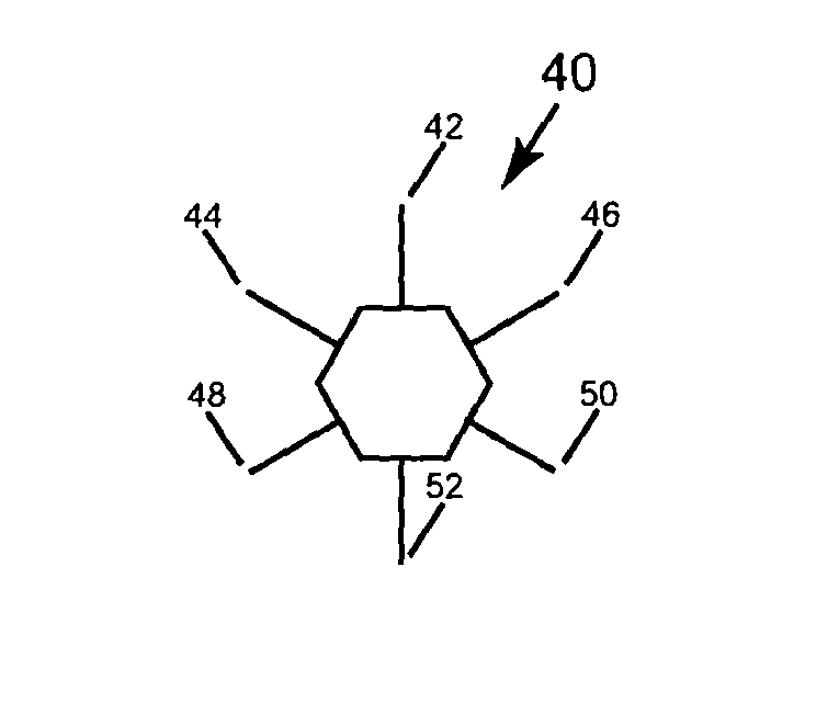
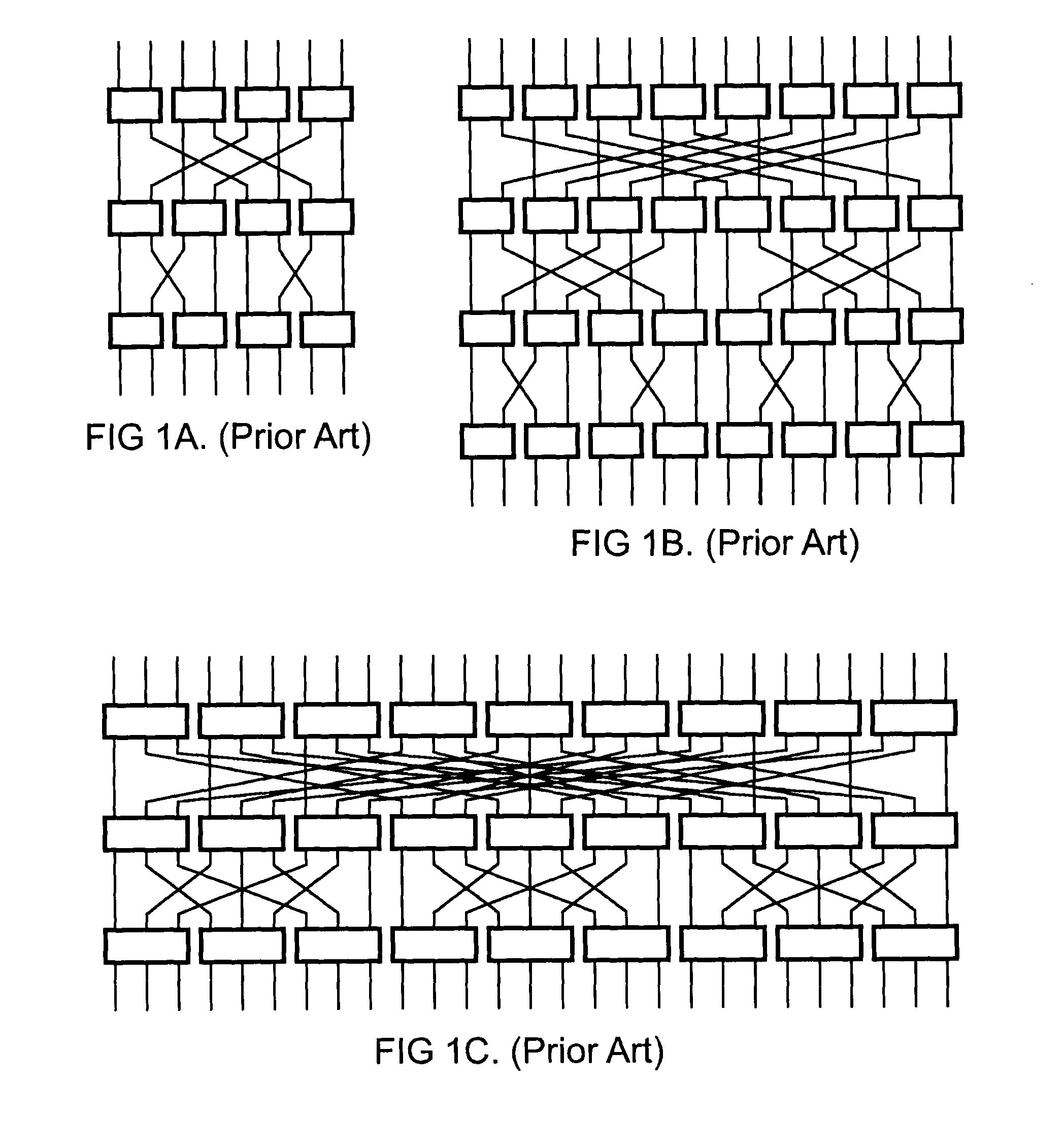
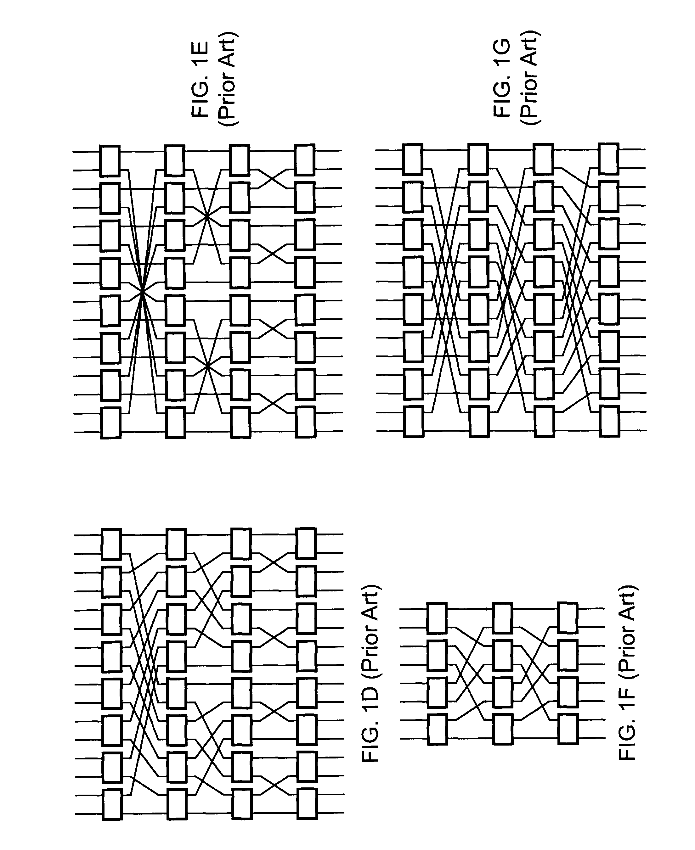
[0115]Switching elements are any type of device configured to relay traffic through different paths depending on the destination address of the traffic. Depending on the context, the switching elements as well as the systems and methods recited within this disclosure, operate with both circuit switched networks, packet switched networks, and networks comprising circuit switched elements and packet switched elements. The switching elements include but aren't limited to routers and switches, such as an Asynchronous Transfer Mode (ATM) switch or Ethernet switch. A switching element comprises ports which are an interface by which traffic is allowed to flow.

[0116]Some switching elements can further have the capability of expanding in the number of ports. In some embodiments, the switching elements can have the number of ports expanded without requiring the switching element to be powered off and in fact, the switching elements can even relay traffic during the expansion process, known as...


PUM


Abstract

An overlaid switching network is derived by overlaying perpendicularly one multistage interconnection network with a second multistage interconnection network. The new network is formed by placing a switching element corresponding to the position of switching elements in either multistage interconnection network. Each switching element in the overlaid network has the ports defined by the two multistage interconnection networks as does its interconnection networks. A special case occurs when the number of rows and columns of the first multistage interconnection network is the number of columns and rows of the second multistage interconnection network, respectively. The overlaid switching networks also inherit their upgradeability from the multistage interconnection networks from which they are derived, such as in the case of a redundant blocking compensated cyclic group multistage network.

Description

RELATED APPLICATIONS[0001]This application is a continuation-in-part of U.S. patent application Ser. No. 10 / 786,874, entitled “Systems and Methods for Upgradeable Scalable Switching”, filed on Feb. 24, 2004, which is incorporated herein by reference in its entirety as if set forth in full. The parent application claims priority under 35 U.S.C. §119 to U.S. Provisional Patent Application Ser. No. 60 / 450,133 entitled, “Systems and Methods for Upgradeable Scalable Switching and its Applications,” filed on Feb. 25, 2003, which is incorporated herein by reference in its entirety as if set forth in full. This parent application is also a continuation-in-part of U.S. Pat. No. 6,901,071 issued on May 31, 2005, which is incorporated herein by reference in its entirety as if set forth in full. This parent application is also a continuation-in-part of U.S. Pat. No. 7,123,612 issued on Oct. 17, 2006, which is incorporated herein by reference in its entirety as if set forth in full. This parent ...

Claims


Application Information

Patent Timeline
Patent Type & Authority Patents(United States)
IPC IPC(8): H04L12/50
CPCH04L1/22H04Q3/68H04Q2213/1302H04Q2213/13166H04Q2213/13167H04L2001/0092H04Q2213/1304
Inventor LU, HAW-MINNHUANG, ALAN
Owner LU HAW MINN
Why Eureka
Try Eureka