Vacuum pump

a vacuum pump and pump body technology, applied in the field of vacuum pumps, can solve the problems of less efficient mechanism, reduce the number of radial interactions, and increase the depth of the radial blades

Inactive Publication Date: 2013-03-12
EDWARDS LTD
View PDF37 Cites 2 Cited by
  • Summary
  • Abstract
  • Description
  • Claims
  • Application Information

AI Technical Summary

Benefits of technology

[0008]Thus, the second, turbo-molecular pumping section 20, for example, of the known pump described with reference to FIG. 1 can be effectively replaced by a pumping section having an externally threaded, or helical, rotor. In such an arrangement, the inlet of the helix will behave in use like a rotor of a turbo-molecular stage, and thus provide a pumping action through both axial and radial interactions. In comparison, a Holweck mechanism with a static thread, such as that indicated at 22 in FIG. 1, pumps fluid by nominally radial interactions between the thread and cylinder. Beyond a certain radial depth of thread, this mechanism becomes less efficient due to the reducing number of radial interactions, and it is for this reason that the typical capacity of a “static” Holweck mechanism is limited to less than that of an equivalent diameter turbo-molecular stage, which pumps by nominally axial interactions and has greater radial blade depths. By providing an externally threaded rotor, the inlet of the thread of the externally threaded rotor can be made much deeper radially than the helical groove in a static Holweck mechanism, resulting in a significantly higher pumping capacity. By appropriate design, the capacity of an externally threaded, deep grooved helical rotor can be comparable to that of an equivalent diameter turbomolecular stage when operating at low inlet pressures, for example below 10−3 mbar. The advantage of the use of such a deep groove helical rotor in place of a turbomolecular stage is that it can offer a higher capacity at higher inlet pressures (above 10−3 mbar) with lower levels of power consumption / heat generation—a limiting factor of the operational window of turbomolecular pumps. By utilising a deep groove helical rotor and raising the inlet pressure above that which would be ideal for a turbomolecular pump, more flow can be pumped without requiring an increase in effective pumping capacity, thus meeting the requirements of increased evacuated system performance without increasing the size of the pump envelope.
[0009]Minimising the increase in pump size / length whilst increasing the system performance where required can make the pump particularly suitable for use as a compound pump for use in differentially pumping multiple chambers of a bench-top mass spectrometer system requiring a greater mass flow rate at, for example, the middle chamber to increase the sample flow rate into the analyser with a minimal or no increase in pump size.
[0010]Furthermore, offering static surfaces adjacent to the outlet of the helical rotor stage, by providing a third pumping section having a helical groove formed in a stator thereof, can further optimise pump performance.
[0011]As the molecules transfer from the inlet side of the rotor towards the outlet side, the pumping action is similar to that of a static Holweck mechanism, and is due to radial interactions between rotating and stationary elements. Therefore, the helical rotor preferably has a tapering thread depth from inlet to outlet (preferably deeper at the inlet side than at the outlet side). Furthermore, the helical rotor preferably has a different helix angle at the inlet side than at the outlet side; both the thread depth and helix angle are preferably reduced smoothly along the axial length of the pumping section from the inlet side towards the outlet side.

Problems solved by technology

Beyond a certain radial depth of thread, this mechanism becomes less efficient due to the reducing number of radial interactions, and it is for this reason that the typical capacity of a “static” Holweck mechanism is limited to less than that of an equivalent diameter turbo-molecular stage, which pumps by nominally axial interactions and has greater radial blade depths.

Method used


Image

  • Vacuum pump
  • Vacuum pump
  • Vacuum pump

Examples


Embodiment Construction

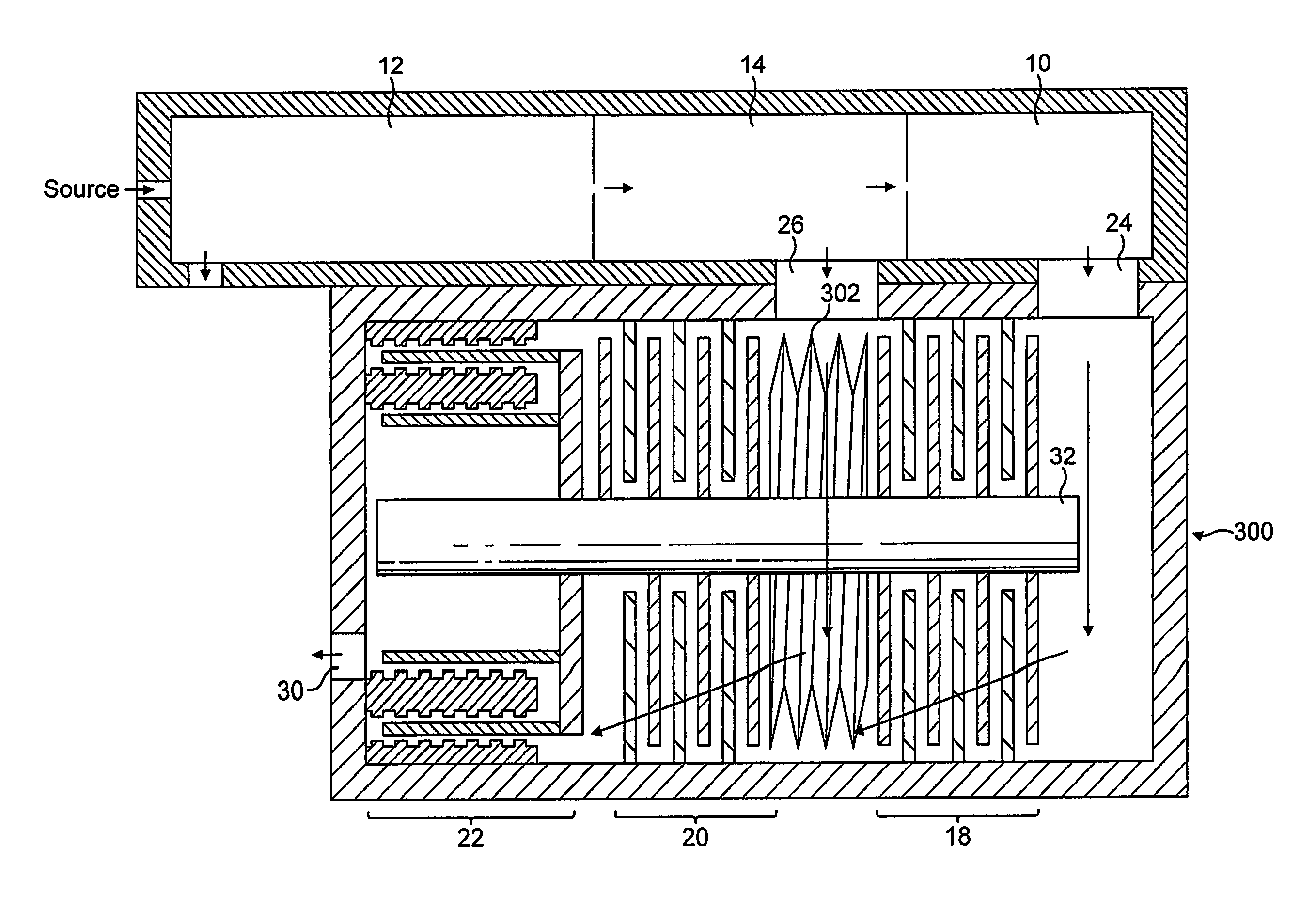
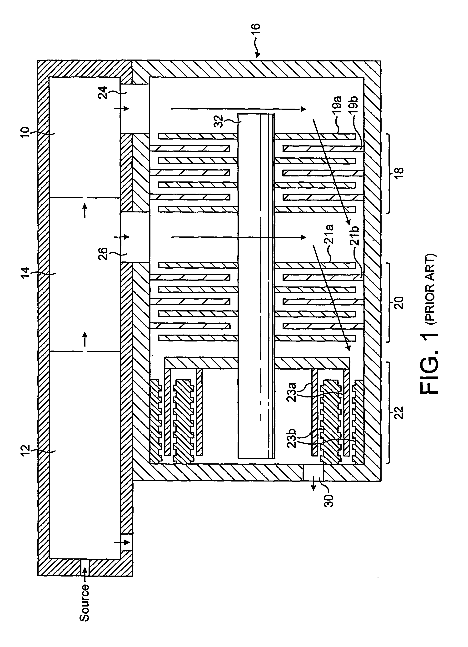
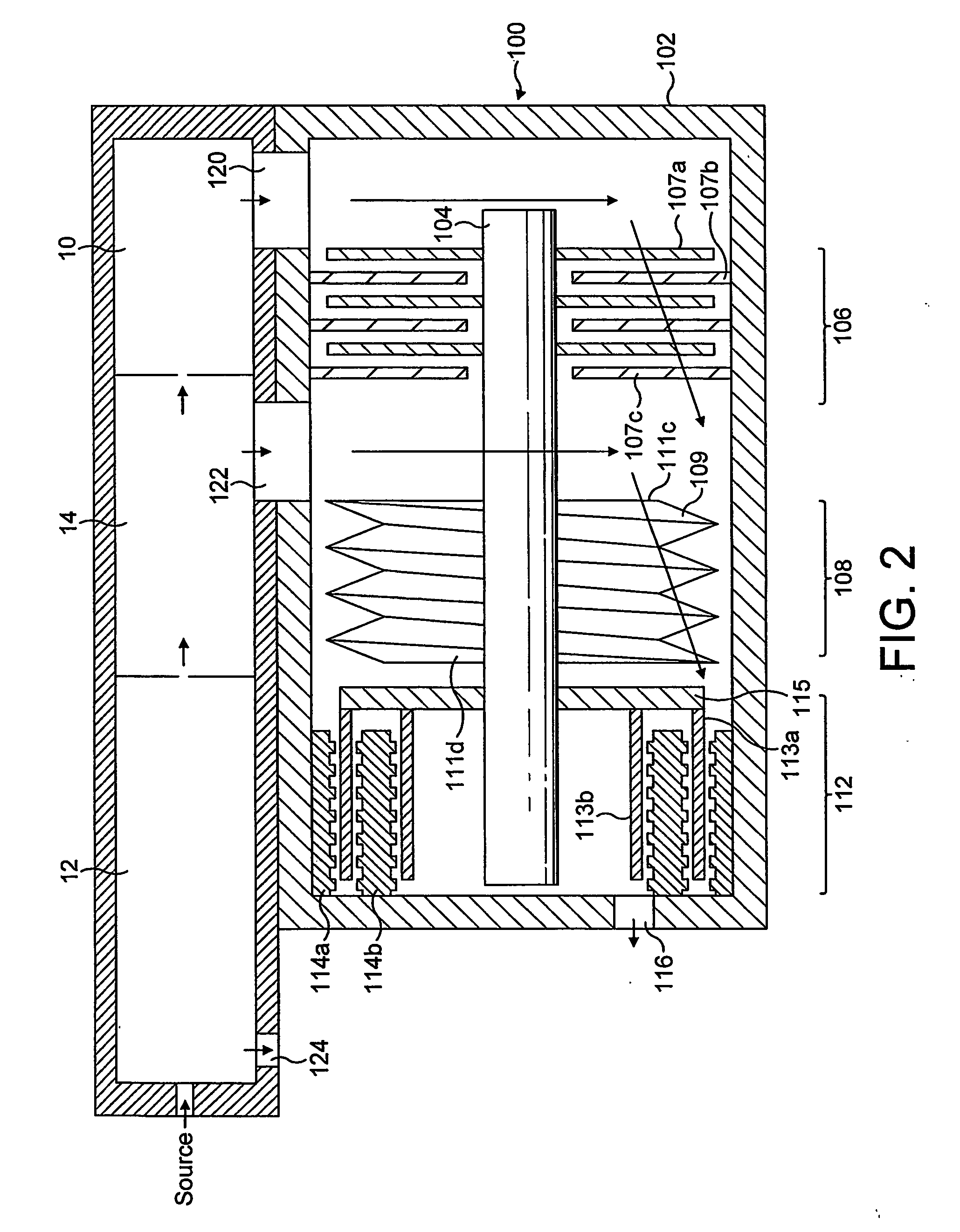
[0025]With reference to FIG. 2, a first embodiment of a vacuum pump 100 suitable for evacuating at the least the high vacuum chamber 10 and intermediate chamber 14 of the differentially pumped mass spectrometer system described above with reference to FIG. 1 comprises a multi-component body 102 within which is mounted a shaft 104. Rotation of the shaft is effected by a motor (not shown), for example, a brushless dc motor, positioned about the shaft 104. The shaft 104 is mounted on opposite bearings (not shown). For example, the drive shaft 104 may be supported by a hybrid permanent magnet bearing and oil lubricated bearing system.

[0026]The pump includes three pumping sections 106, 108 and 112. The first pumping section 106 comprises a set of turbo-molecular stages. In the embodiment shown in FIG. 2, the set of turbo-molecular stages 106 comprises three rotor blades and three stator blades of known angled construction. A rotor blade is indicated at 107a and a stator blade is indicate...


PUM


Abstract

A vacuum pump comprises a first pumping section (106), and, downstream therefrom, a second pumping section (108), The pump comprises a first pump inlet (120) through which fluid can enter the pump and pass through both the first and second pumping sections towards a pump outlet, and a second pump inlet (122) through which fluid can enter the pump and pass through only the second pumping section towards the outlet. The second pumping section (108) comprises an externally threaded rotor (109).

Description

FIELD OF THE INVENTION[0001]This invention relates to a vacuum pump and in particular a compound vacuum pump with multiple ports suitable for differential pumping of multiple chambers.BACKGROUND OF THE INVENTION[0002]In a differentially pumped mass spectrometer system a sample and carrier gas are introduced to a mass analyser for analysis. One such example is given in FIG. 1. With reference to FIG. 1, in such a system there exists a high vacuum chamber 10 immediately following first and second evacuated interface chambers 12, 14. The first interface chamber 12 is the highest-pressure chamber in the evacuated spectrometer system and may contain an orifice or capillary through which ions are drawn from the ion source into the first interface chamber 12. The second, interface chamber 14 may include ion optics for guiding ions from the first interface chamber 12 into the high vacuum chamber 10. In this example, in use, the first interface chamber 12 is at a pressure of around 1 mbar, th...

Claims


Application Information

Patent Timeline
Patent Type & Authority Patents(United States)
IPC IPC(8): F01D3/02F04D19/04
CPCF04D19/046
Inventor STONES, IAN DAVIDGOODWIN, DAVID JOHN
Owner EDWARDS LTD
Why Eureka
Try Eureka