Air cleaner

a technology for air cleaners and cleaners, applied in the field of air cleaners, can solve the problems of insufficient achievement of the desired air cleaning function and improper compacting of the air cleaner structure, and achieve the effect of compact and simple structur

Active Publication Date: 2013-03-12
ROKI CO LTD
View PDF2 Cites 18 Cited by
  • Summary
  • Abstract
  • Description
  • Claims
  • Application Information

AI Technical Summary

Benefits of technology

[0014]The present invention was conceived in consideration of the circumstances encountered in the prior art mentioned above, and an object thereof is to provide an air cleaner capable of surely maintaining engagement between a case and a cover at a predetermined opening angle with a compact and simple structure.
[0028]According to the air cleaner of the present invention of the structures and characters mentioned above, there is provided the engagement maintaining mechanism on one or both side surfaces of the cover and the case so as to maintain the engagement between the case and the cover in a range in which the cover closes the case and in a range in which the cover is opened by a predetermined angle. Accordingly, the air cleaner can be made compact in an entire structure, thus being effective and advantageous.

Problems solved by technology

Since the filter element is provided with a function for filtrating outer (ambient) air taken into the internal combustion engine, it is necessary to periodically exchange the filter element with new one because the filtrating function becomes deteriorated for a long time use of the internal combustion engine.
Such filter element exchanging working is generally performed under a condition such that the air cleaner is disposed in an engine room of an automobile in which an internal combustion engine and many other machineries or components, and under the condition, if the filter element is exchanged, in a certain case, it is impossible to visually observe the engaging condition of the hinge structure between the case and the cover, and in an adverse case, the filter element exchanging working may have been completed with the hinge structure being disengaged, which results in insufficient achievement of desired air cleaning function, thus being inconvenient.
However, according to the structures of the conventional air cleaners mentioned above, the hinge structure is made enlarged, thus being improper for making compact the structure of the air cleaner.

Method used


Image

  • Air cleaner
  • Air cleaner
  • Air cleaner

Examples


Embodiment Construction

[0040]A preferred embodiment of the present invention will be described hereunder with reference to the accompanying drawings. Further, it is to be noted that the described embodiment does not limit the invention defined in respective appended claims, and all the combination of the subject features explained in the embodiment is not essential for the solution of the present invention. It is further to be noted that terms “upper”, “lower”, “right”, “left” and like terms showing direction are used in the present specification based on illustration of the drawings.

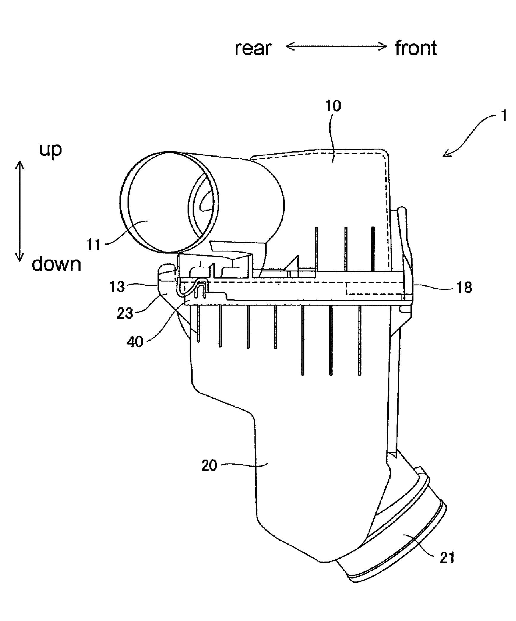
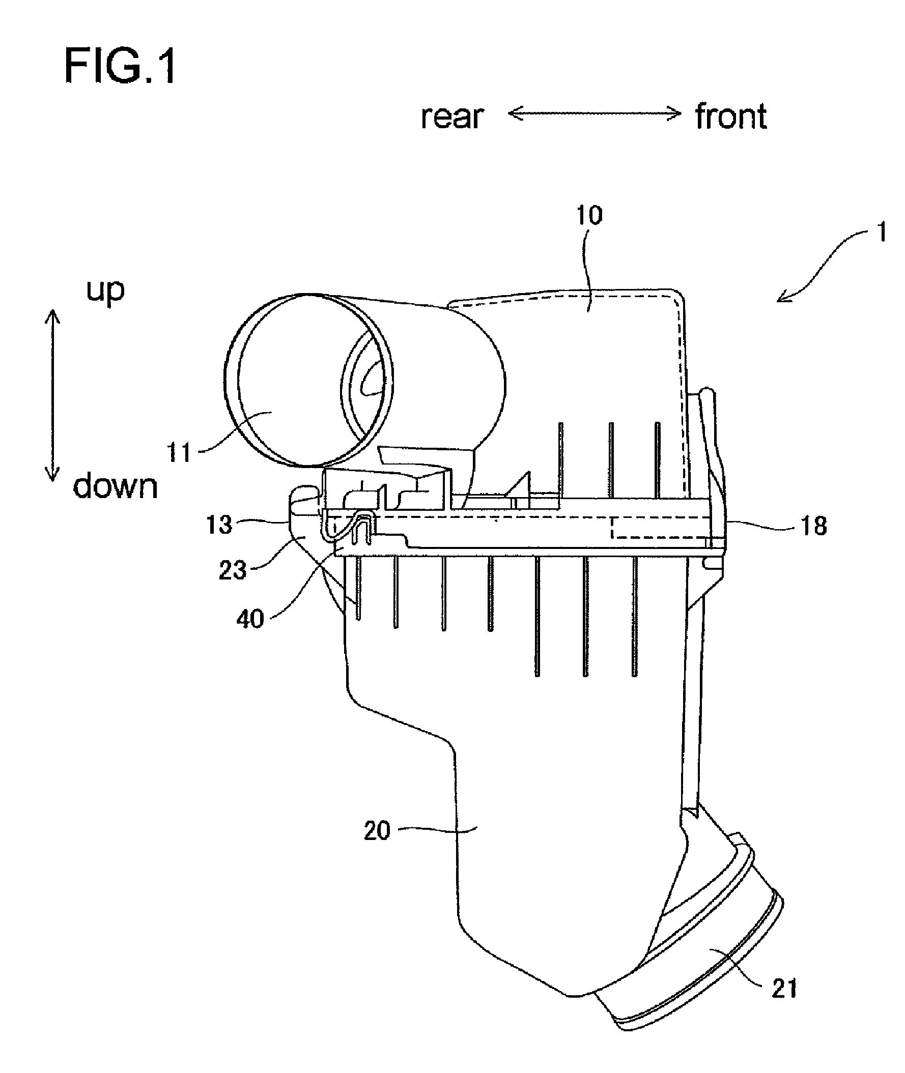
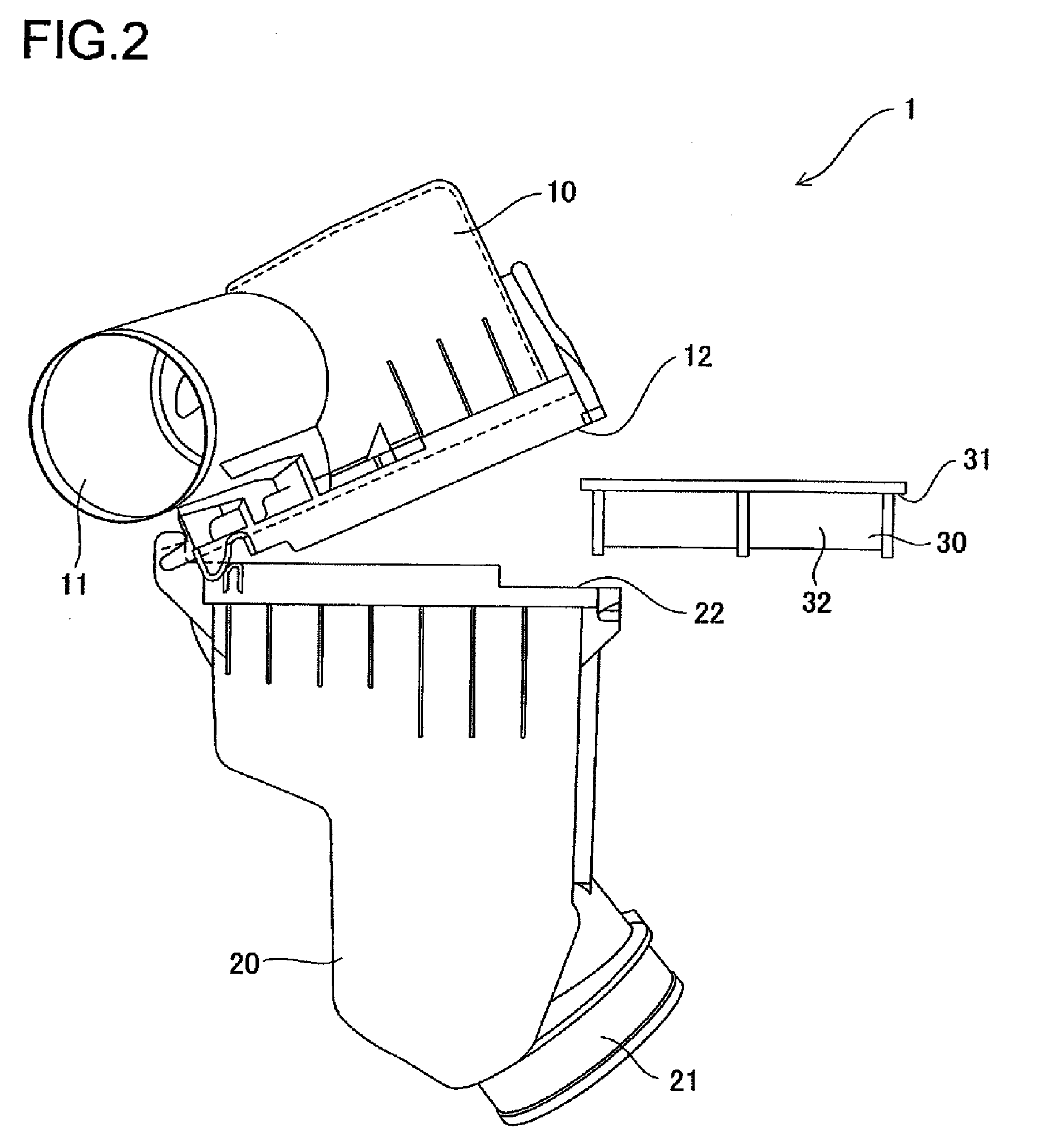
[0041]With reference to FIGS. 1 and 2, an air cleaner 1 according to an embodiment of the present invention is provided with a case 20 in which a filter element 30 is housed and a cover 10 for opening or closing an upper portion of the case 20.

[0042]The cover 10 has a bottomed cylindrical structure having an opening 12 formed to a lower side thereof, and the interior of the cover 10 and the exterior thereof are communicated t...


PUM

PropertyMeasurementUnit
distanceaaaaaaaaaa
angleaaaaaaaaaa
radiusaaaaaaaaaa

Abstract

An air cleaner is provided with: a case in which a filter element is housed and which has an opening; a cover that covers the opening of the case to be opened or closed; a hinge structure having a hinge formed to the cover and a hinge receiver formed to the case to be engaged with the hinge in a detachable manner such that the cover is pivotal around the hinge with respect to the case; and an engagement maintaining mechanism provided to side surfaces of the case and the cover so as to maintain the engagement between the case and the cover in a range in which the cover closes the case and in a range in which the cover is opened by a predetermined angle.

Description

BACKGROUND OF THE INVENTION[0001]1. Field of The Invention[0002]The present invention relates to an air cleaner, and more particularly, to an air cleaner provided with an engagement maintaining mechanism for maintaining engagement of a cover capable of improving maintenance or like workability at a time of exchanging a filter element.[0003]2. Related Art[0004]In a conventionally known air cleaner for an internal combustion engine, a case and a cover are mutually connected by means of hinge structure constructed by a hinge and a hinge receiver, and these members are rotated to be opened or closed.[0005]In the air cleaner of this structure, an intake port is formed to either one of the case or cover and an exhaust port is formed to the other one thereof. The intake port and the exhaust port are constructed such that an outer edge of the filter element is held by the case and the cover so as to be communicated with each other through the filter element, which is disposed between the ca...

Claims


Application Information

Patent Timeline
Patent Type & Authority Patents(United States)
IPC IPC(8): B01D46/00
CPCF02M35/0203B01D46/0004
Inventor SHIMOMURA, CHIKARAKODA, YOSHITAKA
Owner ROKI CO LTD
Why Eureka
Try Eureka