Adaptive nanotopography sculpting

a nanotopography and sculpting technology, applied in the field of adaptive nanotopography sculpting, can solve the problems of compromising the quality of planarization, limiting the degree of planarity attainable by current schemes, and increasing the complexity of the planarization process

Active Publication Date: 2013-03-12
BOARD OF RGT THE UNIV OF TEXAS SYST
View PDF13 Cites 39 Cited by
  • Summary
  • Abstract
  • Description
  • Claims
  • Application Information

AI Technical Summary

Problems solved by technology

The degree of planarity attainable by current schemes, however, may be limited.
Preventive techniques, such as dummy fill and patterned resist, may be used to reduce the variation in pattern density, however, such techniques increase the complexity of the planarization process.
The quality of planarization, however, may be compromised by pattern density variation.
The reflow may be limited due to the high viscosity of the material and / or mobility of the material due to the thin channel formed between the ultra-flat surface and the substrate.
Additionally, fluidic forces between the ultra-flat surface and the substrate may cause tensile stress in the fluid film.
This stress may be relieved when the ultra-flat surface is removed leading to deterioration in surface planarity.
Moreover, CP generally does not cater for large variations in feature density.
For example, if there is a large area in a die with low pattern density, the material may not be able to reflow to fill in the void and thus may affect global planarity.
Additionally, CP generally does not account for difference in surface topography of a substrate and / or the ultra-flat surface.
Use of a very thick film of material may improve mobility of fluid, however, it may be difficult to transfer the same planarity to the substrate as non-uniformity of subsequent material removal processes (e.g., etching, polishing, etc.) may be dominant with thicker films.

Method used


Image

  • Adaptive nanotopography sculpting
  • Adaptive nanotopography sculpting
  • Adaptive nanotopography sculpting

Examples


Embodiment Construction

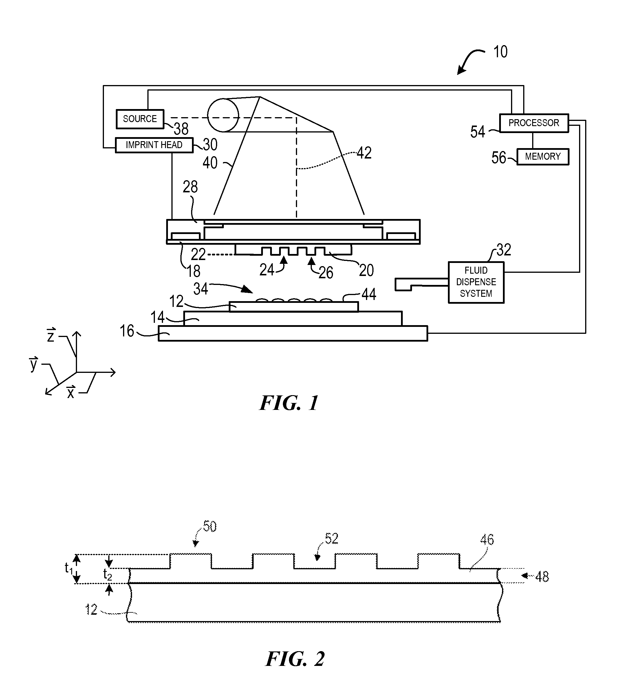
[0021]Referring to the figures, and particularly to FIG. 1, illustrated therein is a lithographic system 10 used to form a relief pattern on substrate 12. Substrate 12 may be coupled to substrate chuck 14. As illustrated, substrate chuck 14 is a vacuum chuck. Substrate chuck 14, however, may be any chuck including, but not limited to, vacuum, pin-type, groove-type, electromagnetic, and / or the like. Exemplary chucks are described in U.S. Pat. No. 6,873,087, which is hereby incorporated by reference.

[0022]Substrate 12 and substrate chuck 14 may be further supported by stage 16. Stage 16 may provide motion along the x-, y-, and z-axes. Stage 16, substrate 12, and substrate chuck 14 may also be positioned on a base (not shown).

[0023]Spaced-apart from substrate 12 is a template 18. Template 18 may include a mesa 20 extending therefrom towards substrate 12, mesa 20 having a patterning surface 22 thereon. Further, mesa 20 may be referred to as mold 20. Alternatively, template 18 may be for...


PUM

PropertyMeasurementUnit
roughnessaaaaaaaaaa
roughnessaaaaaaaaaa
roughnessaaaaaaaaaa

Abstract

Adaptive imprint planarization provides a surface having desired shape characteristics. Generally, topography of a first surface is mapped to provide a density map. The density map is evaluated to provide a drop pattern for dispensing polymerizable material on the first surface. The polymerizable material is solidified and etched to provide a second surface having the desired shape characteristics. Additionally, adaptive imprint planarization compensates for parasitic effects of the imprinting process.

Description

CROSS REFERENCE TO RELATED APPLICATION[0001]This application claims the benefit under 35 U.S.C. §119(e)(1) of U.S. Provisional No. 61 / 060,007, filed Jun. 9, 2008, which is hereby incorporated by reference.BACKGROUND INFORMATION[0002]Nano-fabrication includes the fabrication of very small structures that have features on the order of 100 nanometers or smaller. One application in which nano-fabrication has had a sizeable impact is in the processing of integrated circuits. The semiconductor processing industry continues to strive for larger production yields while increasing the circuits per unit area formed on a substrate, therefore nano-fabrication becomes increasingly important. Nano-fabrication provides greater process control while allowing continued reduction of the minimum feature dimensions of the structures formed. Other areas of development in which nano-fabrication has been employed include biotechnology, optical technology, mechanical systems, and the like.[0003]An exemplar...

Claims


Application Information

Patent Timeline
Patent Type & Authority Patents(United States)
IPC IPC(8): C23F1/00
CPCB82Y10/00B82Y40/00G03F7/0002G03F7/70483G03F7/00G03F7/20H01L21/027
Inventor PANGA, AVINASHSREENIVASAN, SIDLGATA V.
Owner BOARD OF RGT THE UNIV OF TEXAS SYST
Why Eureka
Try Eureka