Motor control device

a technology of motor control and control device, which is applied in the direction of motor/generator/converter stopper, electronic commutator, dynamo-electric converter control, etc., can solve the problems of impaired stability of identifying the polarity of the magnetic pole, unstable d-axis voltage, etc., and achieve stably identification, easy control, and easy identification

Inactive Publication Date: 2013-03-12
AISIN AW CO LTD
View PDF15 Cites 3 Cited by
  • Summary
  • Abstract
  • Description
  • Claims
  • Application Information

AI Technical Summary

Benefits of technology

[0014]When a DC bias component of a magnitude causing a motor to be magnetically saturated over a predetermined period is impressed on a d-axis current command, if the DC bias component is positive or negative, a magnetic flux reaches a saturation domain. Since a permanent magnet has the magnetic flux, even when a d-axis current is a nil, the magnetic flux is not a nil. The property of the magnetic flux with respect to the d-axis current is offset in the d-axis direction. Therefore, assuming that when the DC bias component takes on one of positive and negative values, the magnetic flux reaches the saturation domain, when the DC bias component takes on the other value, the magnetic flux lies in an active domain but does not reach the saturation domain. An observation command contains not only the DC bias component but also a high-frequency component. The magnetic flux therefore fluctuates in response to the high-frequency component. At this time, although the magnetic flux largely fluctuates in the active domain, but the magnetic flux does not fluctuate so largely in the saturation domain as in the active domain. Whether the DC bias component is positive or negative when the magnetic flux reaches the saturation domain is determined with the polarity of the magnetic pole of the permanent magnet. In other words, whether the DC bias component is positive or negative when the magnetic flux reaches the saturation domain is determined with whichever of the north (N) and south (S) poles of the permanent magnet is oriented in the positive direction of the d-axis. The fluctuation of the magnetic flux can be observed using a response voltage computed based on a feedback current sent from the motor in response to the observation command. Therefore, based on the relationship of large and small magnitudes between a first amplitude of the response voltage attained during a period during which the DC bias component is positive, and a second amplitude of the response voltage attained during a period during which the DC bias component is negative. Since the polarity of the permanent magnet is not identified during a transient period such as at the positive-to-negative switching timing of the DC bias component, but identified based on a response returned during a period during which the DC bias component is stably positive or negative. Therefore, the identification can be achieved stably. Namely, when the permanent magnet type synchronous motor is stopped, the polarity of the magnetic pole of the motor can be stably identified without use of a rotation sensor.
[0015]The observation command impress block of the motor control device in accordance with the present invention impresses a predetermined high-frequency component as the observation command on the d-axis current command, and positively and negatively symmetrically impresses thereon a DC bias component, which takes on a certain value over a predetermined period and has a magnitude that causes the motor to be magnetically saturated, as the observation command. Preferably, the response voltage is the d-axis voltage command computed based on the feedback current respondent to the observation command. In general, in vector control, differences between current commands in a vector space and feedback currents in the vector space are obtained, and proportional integral (PI) control or proportional integrodifferential (PID) control is performed to compute voltage commands in the vector space. As mentioned above, in order to identify the polarity of a magnetic pole, the high-frequency component and DC bias component are impressed as the observation command in the vector space. When both the components are impressed on the d-axis current command, the observation command can be readily controlled. In addition, since the voltage commands are computed using the feedback currents that are results of response to the observation command, when the voltage command is used as the response voltage, a function of computing the response voltage need not be separately included. Namely, an ordinary vector control function can be utilized in order to compute the response voltage so as to identify the polarity.

Problems solved by technology

However, when the motor is stopped, since the counter-electromotive force is not developed, a high-frequency current or a high-frequency voltage is applied to the motor.
However, at the positive-to-negative switching timing of the d-axis bias current, there is a possibility that a d-axis current may be in a transient state and a d-axis voltage may not be stable.
As a result, there arises a possibility that the stability in identifying the polarity of the magnetic pole may be impaired and erroneous detection may be invited.

Method used


Image

  • Motor control device
  • Motor control device
  • Motor control device

Examples


Embodiment Construction

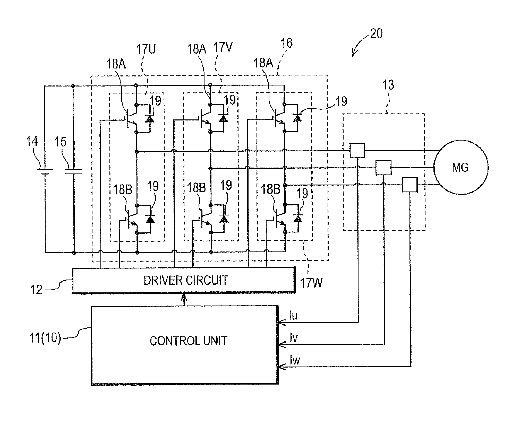
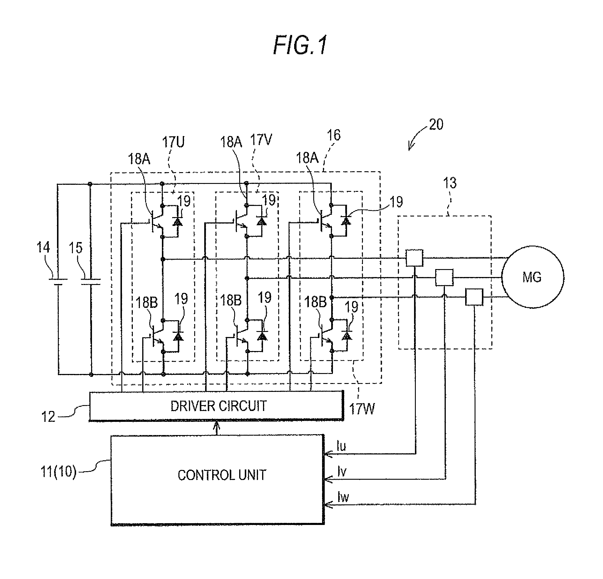
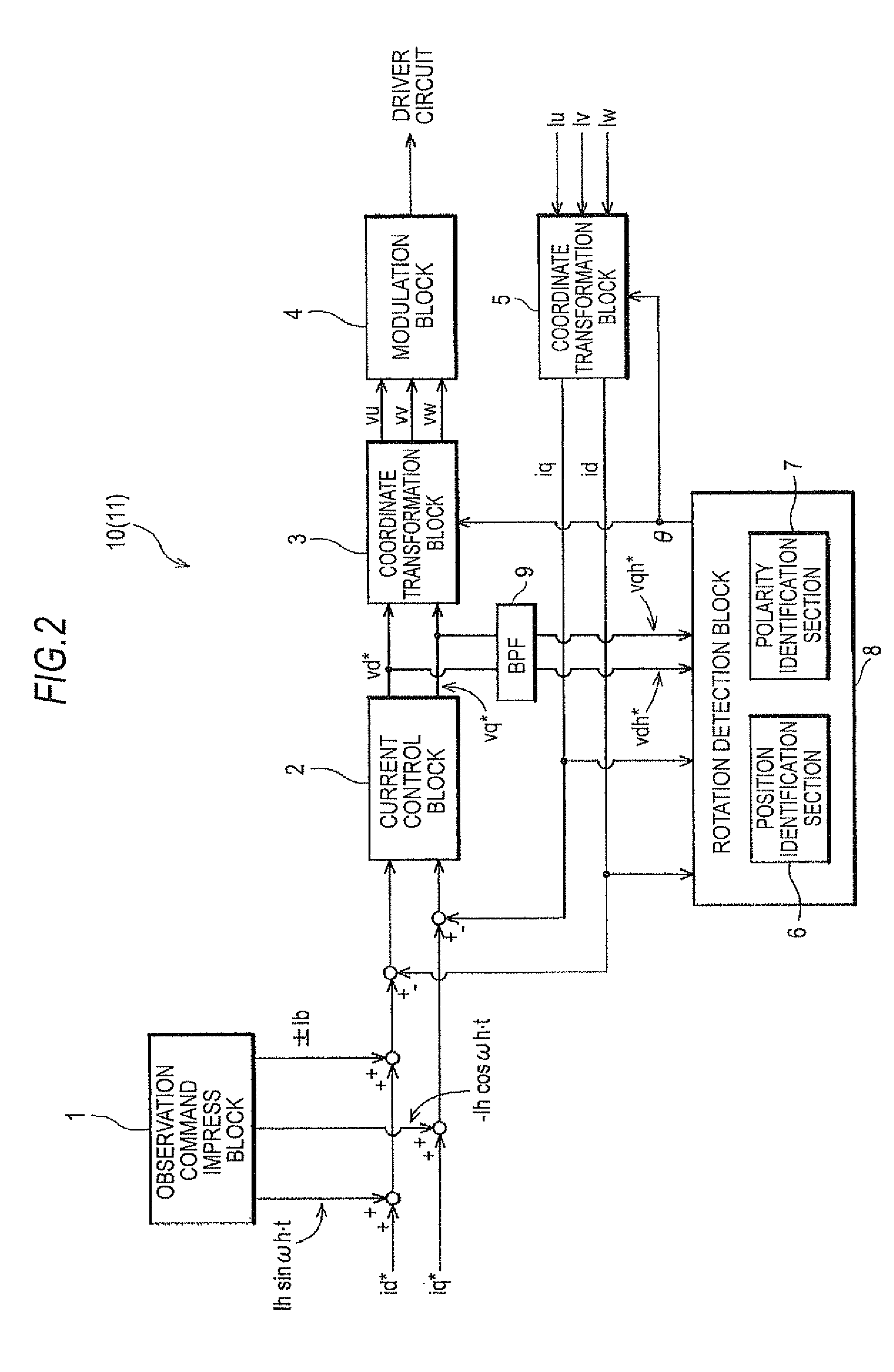
[0024]Referring to the drawings, an embodiment of the present invention will be described below. A motor control device 10 of the present invention is a motor control device that has a function of detecting a magnetic-pole position of an alternating current (AC) motor MG (hereinafter, simply, a motor) without using a rotation sensor such as a resolver, that is, in a so-called sensor-less manner. In the present embodiment, the motor MG is an interior permanent magnet synchronous motor (IPMSM), and has saliency (including reverse saliency) signifying that the magnetic characteristic in an N-pole direction of a permanent magnet of a rotor is electrically different from the magnetic characteristic in a direction perpendicular to the N-pole direction (a direction deviated by an electrical angle of 90°). In the present embodiment, the motor control device utilizes the saliency to identify a magnetic-pole position or the direction of a magnetic pole in a sensor-less manner even when the mo...


PUM


Abstract

A motor control device that has a high-frequency component, and a DC bias component that has a magnitude which causes a motor to be magnetically saturated and take on a certain value over a predetermined period, and is positively and negatively symmetrical are impressed as an observation command on a d-axis current command. The polarity of the magnetic pole of a permanent magnet is identified based on a relationship of large and small magnitudes between a first amplitude, which is attained during a period during which a DC bias component takes on a positive certain value, among amplitudes of a high-frequency component contained in a d-axis response voltage computed based on a feedback current respondent to the observation command, and a second amplitude attained during a period during which the DC bias component takes on a negative certain value.

Description

INCORPORATION BY REFERENCE[0001]The disclosure of Japanese Patent Application No. 2010-072336 filed on Mar. 26, 2010, including the specification, drawings and abstract thereof, is incorporated herein by reference in its entirety.BACKGROUND OF THE INVENTION[0002]1. Field of the Invention[0003]The present invention relates to a motor control device having a function of detecting a magnetic-pole position of a permanent magnet synchronous motor in a sensor-less manner.[0004]2. Description of the Related Art[0005]As a control method for a permanent magnet type synchronous motor, for example, a three-phase synchronous motor, a control method called vector control is known. In the vector control, a motor current flowing into three-phase stator coils of a motor is coordinate-transformed into vector components along a d axis, which lies in a direction of a magnetic field generated by a permanent magnet disposed in a rotor, and a q axis orthogonal to the d axis, whereby feedback control is c...

Claims


Application Information

Patent Timeline
Patent Type & Authority Patents(United States)
IPC IPC(8): H02P6/18H02P6/06H02P6/08H02P6/182H02P6/28
CPCH02P21/0042H02P6/183H02P21/26
Inventor KATO, KOICHINISHIMURA, KEISUKECHEN, ZHIQIANSAHA, SUBRATA
Owner AISIN AW CO LTD
Why Eureka
Try Eureka