
Direct power and stator flux vector control of a generator for wind energy conversion system

a technology of wind energy conversion system and generator, applied in the direction of motors, engine control, wind energy generation, etc., can solve the problems of only valid generator models, power conversion efficiency reduction, and three-phase system instability

Inactive Publication Date: 2013-03-12
VESTAS WIND SYST AS
View PDF18 Cites 24 Cited by
  • Summary
  • Abstract
  • Description
  • Claims
  • Application Information

AI Technical Summary

Benefits of technology

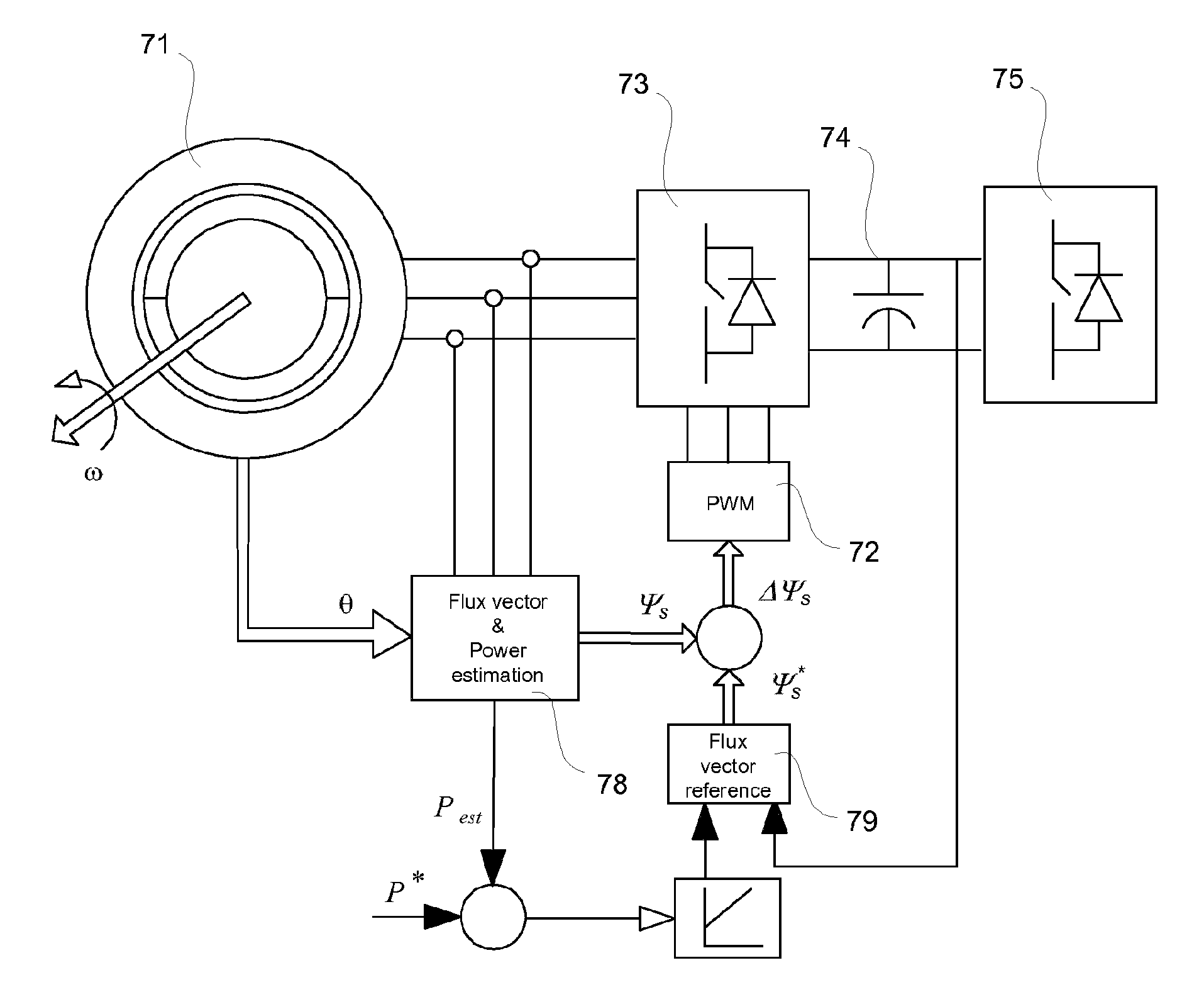
The patent text describes a control system that directly operates switches based on the stator flux in a stationary reference frame. This eliminates the need for an additional transformation into a synchronous reference frame, reducing computational requirements on the control unit. Additionally, there is no constraint to maintain correct decoupling between the flux and torque producing components of the stator currents. The on and off times for the switches can also be determined directly and rapidly from the stator flux difference vector. The technical effects of this system include improved efficiency and responsiveness in controlling the flow of electric current in an electrical system.

Problems solved by technology

This fact result in that any imbalance in the three phase system or any interaction between the phases will not be considered in this type of control.
Moreover, it is evident that the generator model will only be valid during steady state operation of the generator.
This result in a decreased power conversion efficiency as well as a need to oversize the electrical components of the WTG system in order to cope with transient surge currents and voltages.
These include for example (a) a difficulty maintaining correct decoupling between the flux and torque producing components of the stator currents during steady state and dynamics, (b) controlling the currents using linear controllers at higher speeds and higher modulation index.
This may put the controller reliability into stress under extreme conditions of load.

Method used


Image

  • Direct power and stator flux vector control of a generator for wind energy conversion system
  • Direct power and stator flux vector control of a generator for wind energy conversion system
  • Direct power and stator flux vector control of a generator for wind energy conversion system

Examples


Embodiment Construction

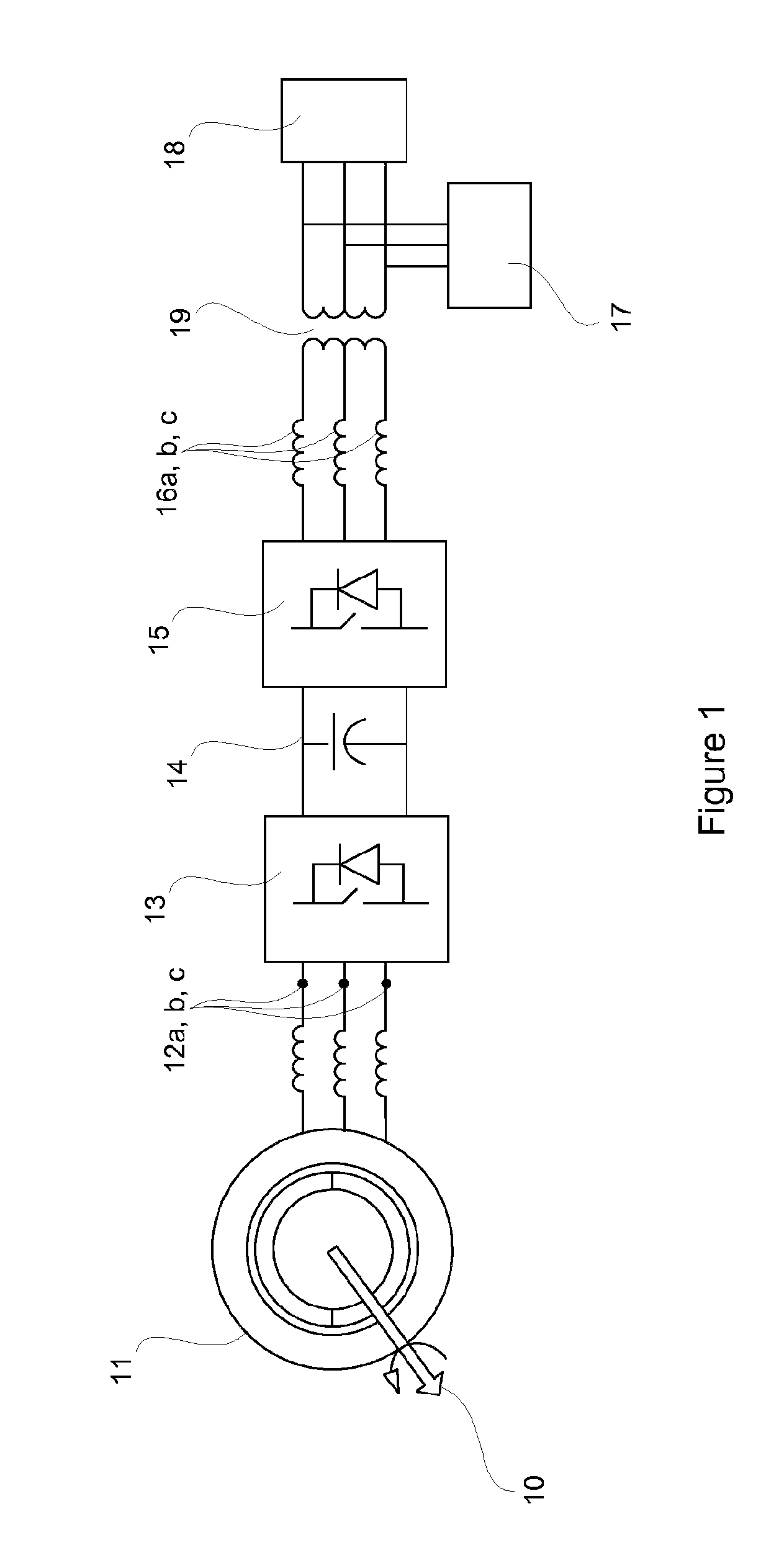
[0062]FIG. 1 illustrates an example of a generator converter system according to a preferred embodiment of the present invention.

[0063]A shaft 10 transfers mechanical energy from an energy source, preferably a set of wind turbine blades (not shown), to a rotor of a variable speed generator 11. The shaft is preferably connected to the wind turbine blades, and to the rotor via a gearbox in order to adapt the rotational speed of the shaft 10 (i.e. speed of the wind turbine blades) to a speed range suitable for the generator 11. The generator 11 then converts the mechanical energy provided via the shaft 10 into electrical energy and delivers the electrical energy at a set of stator terminals 12a, 12b, 12c. For optimum performance in respect of converting the wind energy into electrical energy the shaft 10 will vary its speed as a function of the wind speed. Since the rotational speed of the rotor of the generator 11 is proportional to the rotational speed of the shaft 10, the amplitude ...


PUM


Abstract

A method for controlling a variable speed wind turbine generator is disclosed. The generator is connected to a power converter comprising switches. The generator comprises a stator and a set of terminals connected to the stator and to the switches of the power converter. The method comprises: determining a stator flux reference value corresponding to a generator power of a desired magnitude, determining an estimated stator flux value corresponding to an actual generator power, determining a difference between the determined stator flux reference value and the estimated stator flux value, and operating said switches in correspondence to the determined stator flux reference value and the estimated stator flux value to adapt at least one stator electrical quantity to obtain said desired generator power magnitude.

Description

CROSS-REFERENCE TO RELATED APPLICATIONS[0001]This application is a continuation of U.S. application Ser. No. 13 / 060,374, filed Feb. 23, 2011, which is the National Stage of International Application No. PCT / EP2009 / 061150, filed Aug. 28, 2009, which claims the benefit of U.S. Provisional Application No. 61 / 093,864, filed Sep. 3, 2008, and claims priority under 35 U.S.C. §119 to European Patent Application No. 08163325.7, filed Aug. 29, 2008. The content of each of these applications is hereby incorporated by reference herein in its entirety for all purposes.TECHNICAL FIELD[0002]The present invention generally relates to power converters, and more specifically to power converters that may be connected to wind turbine generators (WTG) which operate at variable speeds, thereby providing a voltage and current with variable amplitude and frequency.BACKGROUND OF THE INVENTION[0003]Wind has been used for a long time as a source of power and in recent years it has become very common to use t...

Claims


Application Information

Patent Timeline
Patent Type & Authority Patents(United States)
IPC IPC(8): H02P9/00F03D9/00
CPCF03D7/0272F03D9/002H02P9/30H02P21/0035H02P21/12H02P9/48H02P9/305F05B2270/101F05B2270/1016H02P2101/15Y02E10/723Y02E10/725H02P21/22F03D9/25Y02E10/72
Inventor TRIPATHI, ANSHUMANYU, CAO SHUJORGENSEN, ALLAN HOLMHELLE, LARSGUPTA, SAURABH
Owner VESTAS WIND SYST AS
Learn More