
Inertial force sensor

a sensor and sensor technology, applied in the direction of acceleration measurement using interia force, instruments, devices using electric/magnetic means, etc., can solve the problem that the accuracy of fault diagnosis cannot be improved, and achieve the effect of improving the diagnosis accuracy of fault diagnosis, shortening the delay time, and good responsibility

Inactive Publication Date: 2013-03-19
PANASONIC CORP
View PDF36 Cites 2 Cited by
  • Summary
  • Abstract
  • Description
  • Claims
  • Application Information

AI Technical Summary

Benefits of technology

The present invention provides an inertial force sensor that can improve the accuracy of detecting angular speed and diagnosing faults. This is achieved by switching the filter circuit characteristic to shorten the delay time and make the detecting circuit more responsive to pseudo angular speed signals during fault diagnosis.

Problems solved by technology

These are typically delay elements.
The above configuration has the problem that the accuracy of fault diagnosis cannot be improved by shortening the delay time while lowering the cutoff frequency.[Patent Document 1] Unexamined Japanese Patent Publication No. 2002-267448

Method used


Image

  • Inertial force sensor
  • Inertial force sensor
  • Inertial force sensor

Examples


Embodiment Construction

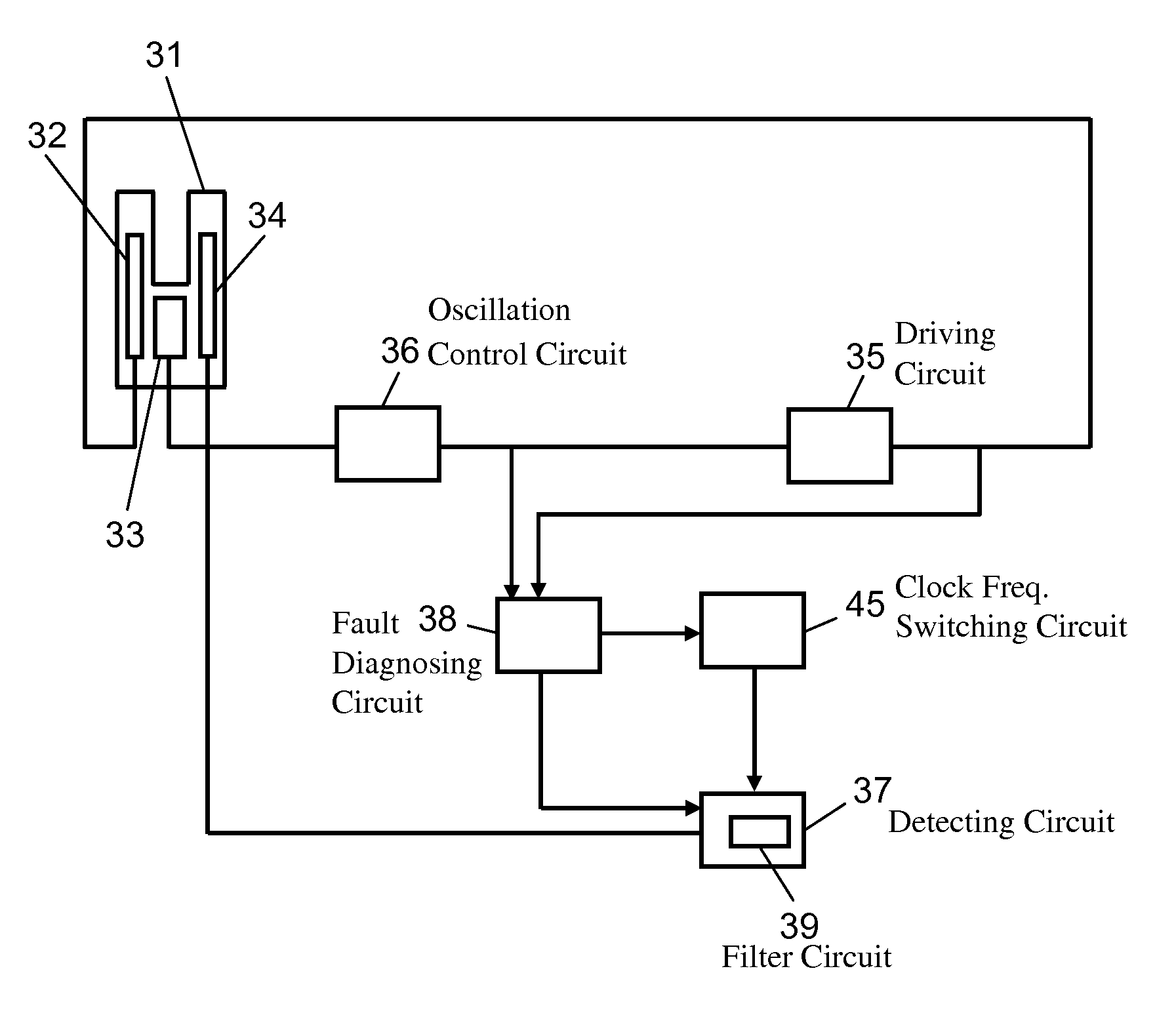
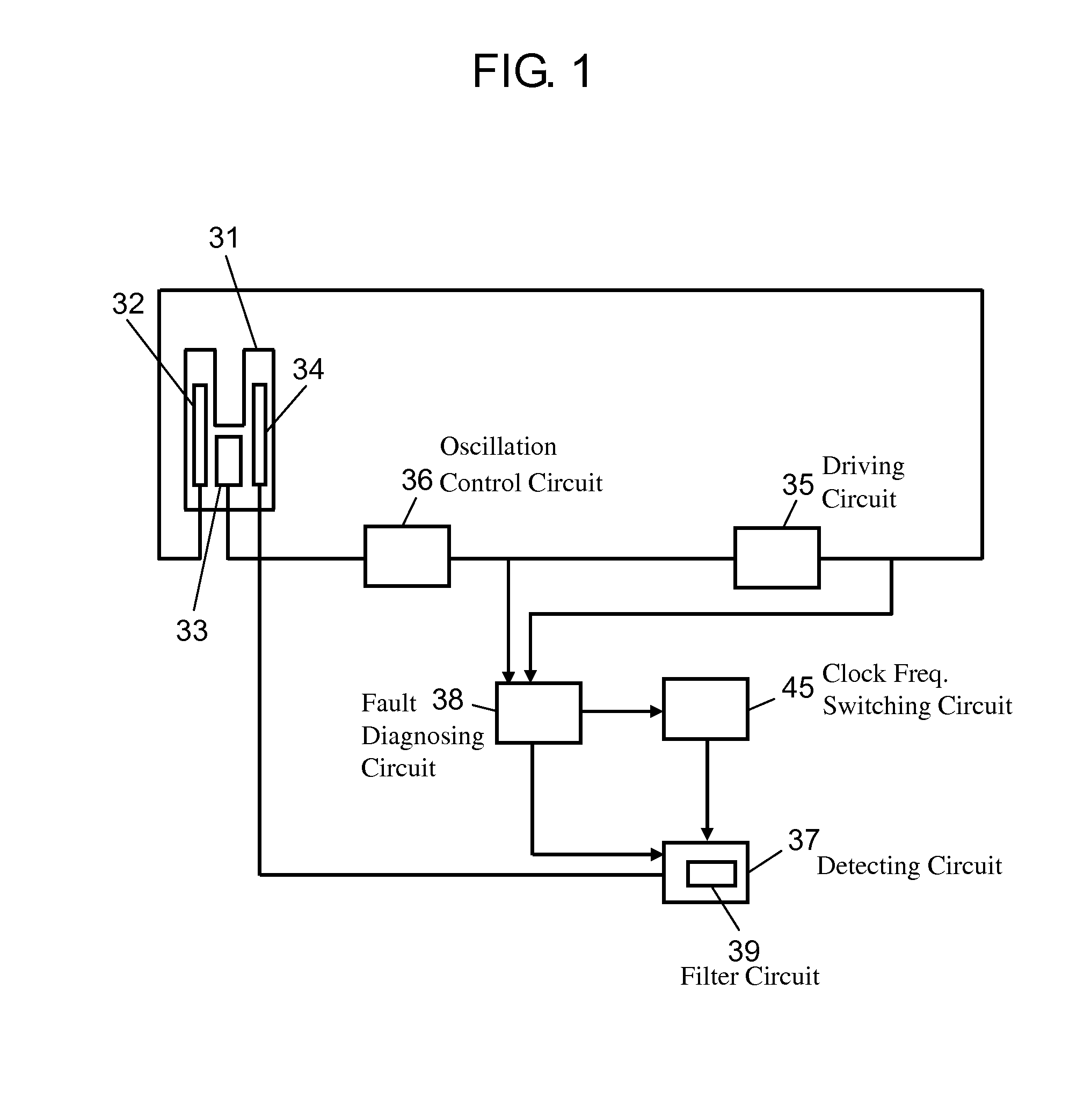
[0057]An inertial force sensor according to an embodiment of the present invention will be described below with reference to the drawings. FIG. 1 is a circuit block diagram of an angular speed sensor according to an embodiment of the present invention. In FIG. 1, the angular speed sensor has oscillator 31 having driving electrode 32, monitor electrode 33, and detecting electrode 34, driving circuit 35, oscillation control circuit 36, detecting circuit 37, and fault diagnosing circuit 38. Driving circuit 35 applies a driving signal to driving electrode 32 to oscillate oscillator 31. Detecting circuit 37 detects an angular speed according to a detecting signal outputted from detecting electrode 34 due to an inertial force. Oscillation control circuit 36 controls an energization amount of the driving signal according to a monitor signal outputted from monitor electrode 33. Fault diagnosing circuit 38 inputs a pseudo angular speed signal to detecting circuit 37 for fault diagnosis.

[0058...


PUM


Abstract

An inertial force sensor which reduces the deterioration of an angular speed detection accuracy and improves the diagnosis accuracy of fault diagnosis is provided.The inertial force sensor includes an oscillator having a driving electrode, a monitor electrode, and a detecting electrode; a driving circuit which applies a driving signal to the driving electrode to oscillate the oscillator; a detecting circuit which detects an angular speed according to a detecting signal outputted from the detecting electrode due to an inertial force; an oscillation control circuit which controls an energization amount of the driving signal according to a monitor signal outputted from the monitor electrode; and a fault diagnosing circuit which inputs a pseudo angular speed signal to the detecting circuit for fault diagnosis, wherein a filter switching circuit which switches a characteristic of a filter circuit included in the detecting circuit in fault diagnosis mode to shorten a delay time is provided.

Description

TECHNICAL FIELD[0001]The present invention relates to an inertial force sensor used in various electronic equipment, for example, used for attitude control, navigation, or the like, of a mobile body such as an aircraft, an automobile, a robot, a watercraft, and a vehicle.BACKGROUND ART[0002]A conventional angular speed sensor will be described below.[0003]FIG. 11 is a circuit block diagram of the conventional angular speed sensor. In FIG. 11, the conventional angular speed sensor has oscillator 1 having driving electrode 2, monitor electrode 3, and detecting electrode 4, driving circuit 5, oscillation control circuit 6, detecting circuit 7, fault diagnosing circuit 8, and filter circuit 9. Driving circuit 5 applies a driving signal to driving electrode 2 to oscillate oscillator 1. Detecting circuit 7 detects an angular speed according to a detecting signal outputted from detecting electrode 4 due to an inertial force. Oscillation control circuit 6 controls an energization amount of ...

Claims


Application Information

Patent Timeline
Patent Type & Authority Patents(United States)
IPC IPC(8): G01C19/00G01C19/5776
CPCG01C25/00G01C19/5776
Inventor KURODA, KEISUKEUEMURA, TAKESHI
Owner PANASONIC CORP
Learn More